10
List of Added Tone-FX
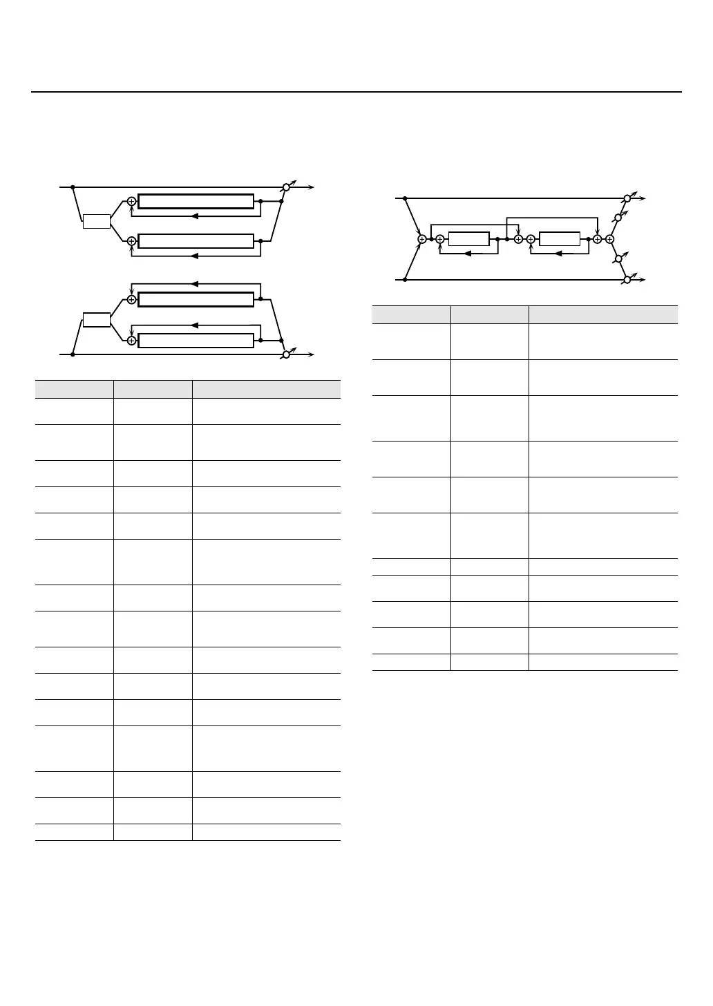
53: 2 Band Step Flanger
A step flanger that lets you apply an effect independently to
the low-frequency and high-frequency ranges.
fig.MFX-34
54: Serial Delay
This delay connects two delay units in series. Feedback can
be applied independently to each delay unit, allowing you to
produce complex delay sounds.
fig.MFX-45
Parameter
Range Explanation
Split Freq 200–8000 Hz
Frequency at which the low and high
ranges will be divided
Low Pre Delay 0.0–100.0 ms
Delay time from when the original
sound is heard to when the low-range
flanger sound is heard
Low Rate
0.05–10.00 Hz,
note
Rate at which the low-range flanger
sound is modulated
Low Depth 0–127
Modulation depth for the low-range
flanger sound
Low Phase 0–180 deg
Spaciousness of the low-range flanger
sound
Low
Feedback
-98– +98%
Proportion of the low-range flanger
sound that is to be returned to the
input (negative values invert the
phase)
Low Step
Rate #1
0.10–20.00 Hz,
note
Rate at which the steps will cycle for
the low-range flanger sound
High Pre Delay 0.0–100.0 ms
Delay time from when the original
sound is heard to when the high-range
flanger sound is heard
High Rate
0.05–10.00 Hz,
note
Rate at which the high-range flanger
sound is modulated
High Depth 0–127
Modulation depth for the high-range
flanger sound
High Phase 0–180 deg
Spaciousness of the high-range
flanger sound
High
Feedback
-98– +98%
Proportion of the high-range flanger
sound that is to be returned to the
input (negative values invert the
phase)
High Step
Rate #2
0.10–20.00 Hz,
note
Rate at which the steps will cycle for
the high-range flanger sound
Balance #3
DRY100:0WET–
DRY0:100WET
Volume balance of the original sound
(DRY) and flanger sound (WET)
Level 0–127 Output volume
R in
R out
L in
L out
Split
High Band Step Flanger
Split
Low Band Feedback
High Band Feedback
High Band Feedback
Low Band Feedback
Low Band Step Flanger
High Band Step Flanger
Low Band Step Flanger
Parameter
Range Explanation
Delay1 Time
0–1300 ms, note
Delay time from when sound is input
to delay 1 until the delay sound is
heard
Delay1
Feedback #1
-98– +98%
Proportion of the delay sound that is to
be returned to the input of delay 1
(negative values invert the phase)
Delay1 HF Damp
200–8000 Hz,
BYPASS
Frequency at which the high-
frequency content of the delayed
sound of delay 1 will be cut (BYPASS:
no cut)
Delay2 Time 0–1300 ms, note
Delay time from when sound is input
to delay 2 until the delay sound is
heard
Delay2
Feedback #2
-98– +98%
Proportion of the delay sound that is to
be returned to the input of delay 2
(negative values invert the phase)
Delay2 HF Damp
200–8000 Hz,
BYPASS
Frequency at which the high-
frequency content of the delayed
sound of delay 2 will be cut (BYPASS:
no cut)
Pan L64–63R Panning of the delay sound
Low Gain -15– +15 dB
Amount of boost/cut for the low-
frequency range
High Gain -15– +15 dB
Amount of boost/cut for the high-
frequency range
Balance #3
DRY100:0WET–
DRY0:100WET
Volume balance of the original sound
(DRY) and delay sound (WET)
Level 0–127 Output volume
R in
R out
L in
L out
Feedback 1
Pan L
Pan R
Delay 1
Feedback 2
Delay 2
V-Synth_GT_v2_e1.book 10 ページ 2008年12月17日 水曜日 午前9時5分
 Loading...