Reference Manual
00809-0100-4792, Rev CA
August 2010
2-3
Rosemount 1495, 1496
Steam Applications
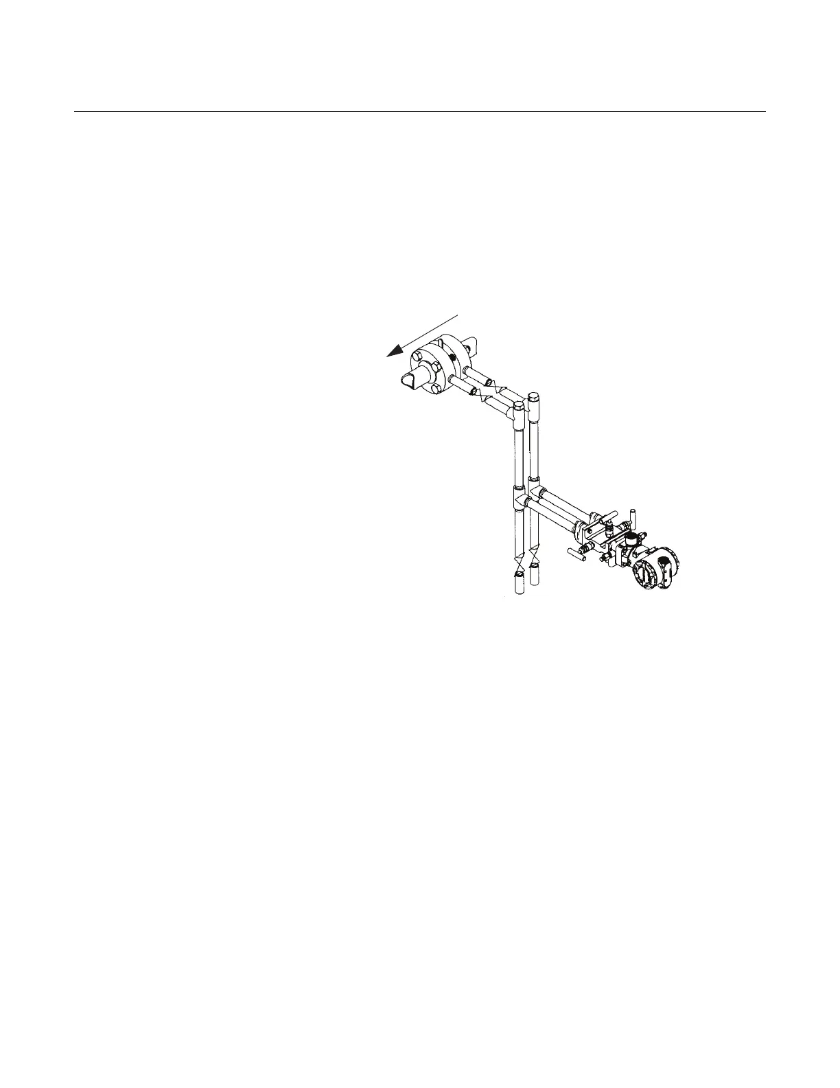
Mount hardware to allow for a water leg in the impulse piping:
• In steam or other elevated temperature services, do not allow the
temperatures at the transmitter process flanges to exceed 300 °F (149
°C).
• Do not blow down impulse piping through the transmitter. Flush the
lines with the blocking valves closed and refill the lines with water
before resuming measurement
• Keep the liquid head balanced on both legs of the impulse piping.
Other Installation Considerations:
• Orient the high side of transmitter to measure upstream of the DP
element.
• Orient the low side of transmitter to measure downstream of the DP
element.
• Temperature taps and thermowells should be located downstream of
the DP element.
• Flow Conditioners and Straighteners are always located upstream of
the DP element. Refer to Appendix B Recommended Installation
Requirements.
• The handle of the orifice plate has the word “Inlet” stamped on the side
that faces upstream.
• To correct for installation effects, the transmitter should be zeroed after
mounting.
STRAIGHT RUN
REQUIREMENTS
To obtain published accuracy, sufficient straight run is required to produce a
fully developed flow profile. Shorter straight run lengths are possible, but
accuracy will be affected. Consult the Factory for further information. Refer to
Appendix B Recommended Installation Requirements for recommended
straight pipe lengths.
Flow