Reference Manual
00809-0100-4792, Rev CA
August 2010
B-9
Rosemount 1495, 1496
ASME MFC-3M-2004 Measurement of Fluid Flow in Pipes Using Orifice, Nozzle, and Venturi
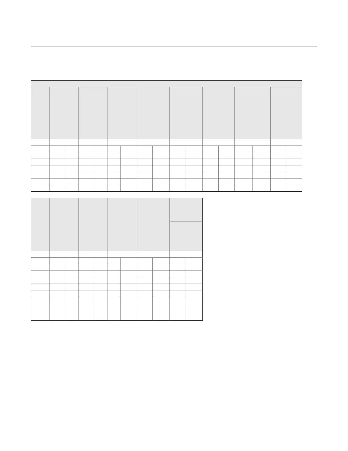
Table B-6. Required Straight Lengths Between Orifice Plates and Fittings Without Flow Conditioners
Upstream (Inlet) Side of Orifice Plate
Diam-
eter
Ratio
Single 90°
bend, Two
90° bends
in any
Plane:
S-Configu-
ration
(S>30D)
(1)
Two 90°
bends in
Same
Plane:
S-Configu-
ration
(30DS>10
D)
(1)
Two 90°
bends in
Same
Plane:
S-Configu-
ration
(10DS)
(1)
Two 90°
bends in
Perpendicular
Planes:
(30DS>5D)
(1)
Two 90
°
bends in
Perpendicular
Planes:
(5DS)
(1)(2)
Single 90°
Tee with or
without
Extension
Mitre 90°
Bend
Single 45°
Bend, Two 45°
Bends in Same
Plane:
S-Configuratio
n (S2D)
(1)
Concentric
Expander 2D
to D Over
Length of
1.5D to 3D
1 2 3 4 5 6 7 8 9
A B A B A B A B A B A B A B A B
0.20 6 3 10
(3)
10
(3)
19 18 34 17 3
(3)
7
(3)
5
(3)
0.40 16 3 10
(3)
10
(3)
44 18 50 25
(3)
3 30
(3)
5
(3)
0.50 22 9 18 10 22 10 44 18 75 34 19 9 30 18 8 5
0.60 42 13 30 18 42 18 44 18 65
(4)
25 29 18 30 18 9 5
0.67 44 20 44 18 44 20 44 20 60 18 36 18 44 18 12 6
0.75 44 20 44 18 44 22 44 20 75 18 44 18 44 18 13 8
Diam-
eter
Ratio
Concentric
Expander
0.5D to D
Over
Length of D
to 2D
Full Bore
Ball Valve
or Gate
Valve Fully
Open
Abrupt
Symmet-
rical
Reduction
Thermometer
Pocket or
Well of
Diameter
0.03D
(5)(6)
Downstream
(outlet) Side
of the Orifice
Plate
Fittings
(Columns 2 to
11) and
Densitometer
Pocket
1 10 11 12 13 14
0.20 A B A B A B A B A B
0.40 6
(3)
12 6 30 15 5 3 4 2
0.50 12 8 12 6 30 15 5 3 6 3
0.60 20 9 12 6 30 15 5 3 6 3
0.67 26 11 14 7 30 15 5 3 7 3.5
0.75 28 14 18 9 30 15 5 3 7 3.5
Diam-
eter
Ratio
36 18 24 12 30 15 5 3 8 4
(1) S is the separation between the two bands measured from the downstream end of the curved portion of the upstream bend to the upstream end
of the curved portion of the downstream bend.
(2) This is not a good upstream installation; a flow conditioner should be used where possible.
(3) The straight length in each Column A gives zero additional uncertainty; data are not available for shorter straight lengths which could be used to
give the required straight lengths for each Column B.
(4) 95D is required for Re
D
X 10
6
if S < 2D.
(5) The installation of thermometer pockets or wells will not alter the required minimum upstream straight lengths for the other fittings.
(6) A thermometer pocket or well of diameter between 0.03D and 0.13D may be installed provided that the values in each Column A and B are
increased to 20 and 10 respectively. Such an installation is not, however, recommended.
GENERAL NOTES:
(a) Values expressed as multiples of internal diameter, D.
(b) The minimum straight lengths required are the lengths between various fittings located upstream or downstream of the orifice plate and the orifice
plate itself. Straight lengths shall be measured from the downstream end of the curved portion of the nearest (or only) bend or of the tee or the
downstream end of the curved or conical portion of the reducer or the expander.
(c) Most of the bends on which the lengths in this table are based had a radius of curvature equal to 1.5D.
(d) Column A for each fitting gives lengths corresponding to “zero additional uncertainty” values [see para. 2-5.2(c)].
(e) Column B for each fitting gives lengths corresponding to “0.5% additional uncertainty” values [see para. 2-5.2(d)].
30D S 5D
a