Reference Manual
00809-0100-4792, Rev CA
August 2010
Rosemount 1495, 1496
B-8
S = Separation distance between elbows, measure as defined in Table A-1.
UL1 = UL - UL2. See Figure A-1.
Note 1: Lengths shown under the UL2 column are the dimensions shown in Figure A-1 and defined in Table A-2.
Note 2:The tolerance on specified lengths for UL, UL2, and DL is ±0.25D
i
.
Note 3: Not allowed means that it is not possible to find an acceptable location for the 1998 Uniform Concentric 19-Tube Bundle Flow
Straightener downstream of the particular fitting for all values of UL.
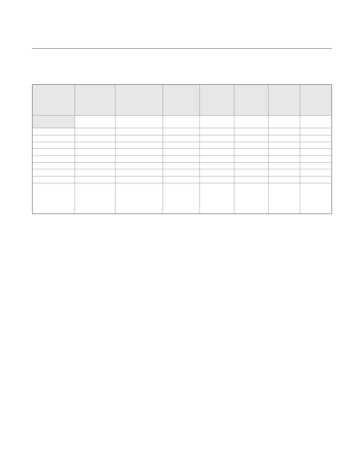
Table B-5. Orifice Meter Installation Requirements With 1998 Uniform Concentric 19-Tube Bundle Flow
Straightener for Meter Tube Upstream Length of .
Single 90° elbow
R/D
i
= 1.5
Two 90° elbows out
of plane
R/D
i
= 1.5
Singe 90° tee
used as an
elbow but not
as a header
element
Partially
closed valves
(at least 50%
open)
High swirl
combined
with single
90° Tee
Any fitting
(catch-all
category)
Downstream
meter tube
length
Diameter Ratio, UL2 UL2 UL2 UL2 UL2 UL2 DL
0.10 5-25 5-25 5-25 5-13 5-23 5-13 2.8
0.20 5-25 5-25 5-25 5-13 5-23 5-13 2.8
0.30 5-25 5-25 5-25 5-13 5-23 5-13 3.0
0.40 5-25 5-25 5-25 5-13 5-23 5-13 3.2
0.50 11.5-25 9-25 9-23 7.5-15 9-19.5 11.5-14.5 3.5
0.60 12-25 9-25 11-16 10-17 11-16 12-16 3.9
0.67 13-16.5 10-16 11-13 10-13 11-13 13 4.2
0.75 14-16.5 12-12.5 12-14 11-12.5 14 Not allowed 4.5
Recommended
tube bundle
location for
maximum range
of
13 12-12.5 12-13 11-12.5 13 13 4.5