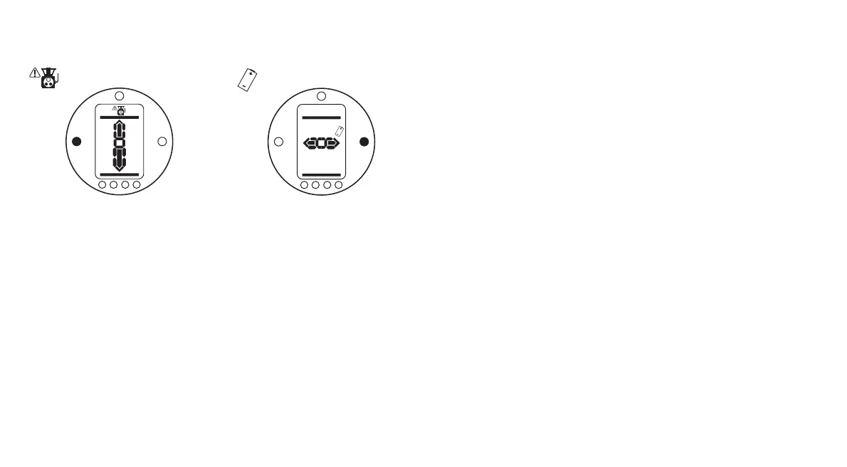
Actuator Alarm
Fig. 3.8
The actuator alarm icon, Fig. 3.8, is
displayed when an active actuator
alarm is present.
Electrical operation will be inhibited
while an alarm is present. The possible
causes are:
• Transformer thermostat tripped
• Battery low on power up*
• Power supply fault
*see Battery Alarm
(To identify the specific cause of the
alarm refer to Help Screens).
Battery Alarm
Fig. 3.9
The battery alarm icon, Fig. 3.9, is
displayed when the actuator detects its
battery as being low, discharged or
missing.
If, on power up, the actuator detects a
discharged battery and actuator power
loss inhibit feature [OS] is enabled
(refer to page 58), both battery and
actuator alarm icons (Fig.3.8 and 3.9)
will be displayed. Electrical operation
will be inhibited.
When the battery alarm icon
is displayed, the battery should be
replaced immediately (refer to page 62).
The actuator checks the battery status
at approximately 10 minute intervals.
After replacing a battery the alarm icon
will continue to be displayed until the
next check indicates the battery is
healthy. This may take up to 10
minutes.
6

 Loading...