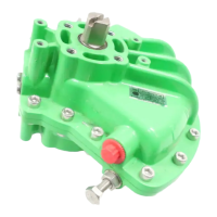
Secure actuator to valve with four fixing
bolts. Check that the cast groove in
actuator base is not obstructed see Fig
5.1. Its purpose is to protect the
actuator in the event of a product leak
from the valve stem/gland packing.
Check base fixing bolts are tight.
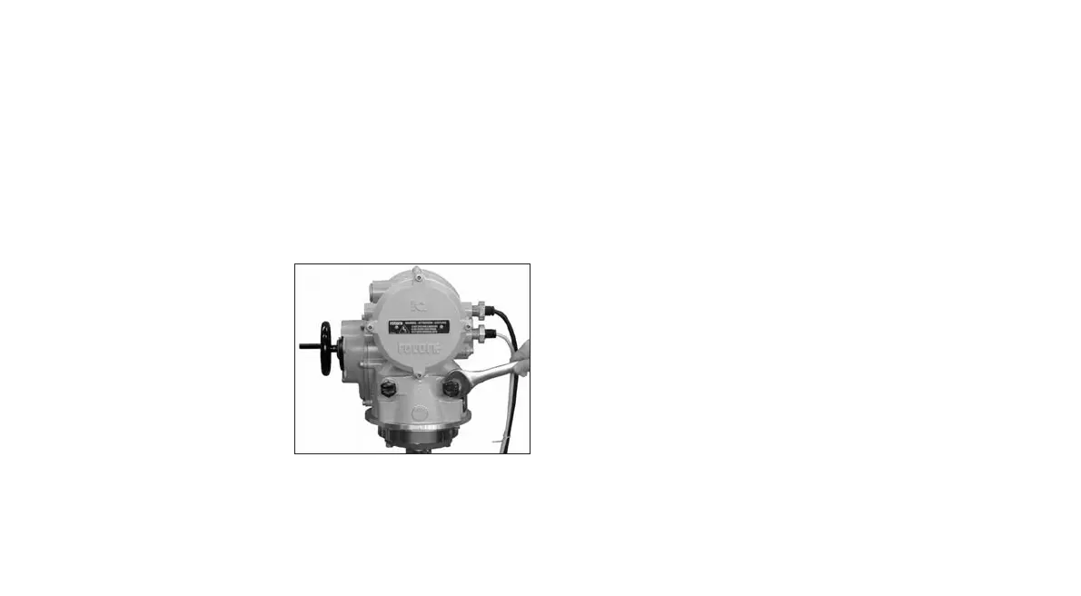
5.6 Stop Bolts
It is recommended that stop bolt
adjustment be carried out by the
valvemaker/supplier before the valve is
fitted into pipework. Once installed, the
valve maker/supplier should be
consulted before stop bolt re-
adjustment is carried out. Stop bolts
can be wired to prevent tampering.
After setting or adjustment of stop
bolts the actuator limits must be reset,
refer to Limits LC, LO page 22.
The IQT stop bolts are located below
the terminal compartment. Stop bolt
adjustment allows +/- 5º variation of
travel at each end position. Screwing
bolts in reduces movement, out
increases movement. For clockwise
closing valves the right hand bolt is the
closed stop as shown with spanner in
fig 5.2. The left is the open stop. Stop
bolts are factory set to give a nominal
90º travel.
Fig. 5.2
Stop Bolt sizes.
IQT 125 to 500: M12 bolt requiring
19mm AF spanner.
IQT1000 & 2000: M20 bolt requiring
30mm AF spanner.
Adjustment for non seating
valves types
For closed and open stop position
adjustment:
Undo stop bolt lock-nut. Move actuator
and valve to the required stopping
position (it may be necessary to
unscrew stop bolt to allow more travel).
Screw stop bolt in until a stop is felt.
Tighten stop bolt lock nut.
Adjustment for seating valves
types
For closed and open stop position
adjustment:
Undo stop bolt lock-nut. Move actuator
and valve to the required seating
position of the valve (it may be
necessary to unscrew stop bolt to allow
more travel). Screw stop bolt in until a
stop is felt and then back off by 3
turns. Tighten stop bolt lock-nut.
Reset actuator limits
Refer to Limits LC, LO page 22.
9

 Loading...