Do you have a question about the RSP STC20 and is the answer not in the manual?
This document provides installation and maintenance instructions for Swivel Tool Changers (STC) models STC20, STC100, STC250, and STC350, along with their corresponding tool attachments and options for power, signal, and air transfer. The STCs are designed to enhance the flexibility and reliability of robot applications by providing robust and safe tool changing capabilities.
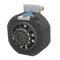
The Swivel Tool Changers are peripheral products for high-performance robot applications, offering complete tool system solutions. They integrate a patented TrueConnect™ locking device with swivel technology, combining robustness, high safety, low weight, and compactness. This design allows for the transfer of compressed air, water, electrical, and data signals, as well as weld and servo power, to the tools while maintaining full robot motion capabilities. The unique Circular Rotators enable free selection of cables and hoses, ensuring high robot flexibility and reduced space requirements. Integrated tool systems are delivered as complete plug-and-play solutions for quick and simple installation.
The STCs facilitate automatic tool changes, allowing a robot to switch between different end-effectors or tools without manual intervention. This capability is crucial for automating complex tasks that require multiple tools, thereby improving productivity and efficiency in manufacturing and assembly lines. The swivel function allows for continuous rotation of the tool, preventing cable and hose entanglement, which is particularly beneficial in applications requiring extensive robot movement.
The installation process for the STC on a robot involves several key steps. First, the robot must be placed in a service position, and power must be switched off and locked out for safety. A guide pin is then pressed into the robot flange to ensure correct alignment. An adaptation plate, if used, is fitted onto the guide pin and secured with screws, tightened to specified torques. The swivel tool changer is then lifted onto the robot flange or adaptation plate, ensuring the guide pin fits into the guide hole of the STC, and secured with screws. Rotation stops are mounted on the STC, with specific tightening torques depending on the model (STC20/STC100 or STC250/STC350). Air hoses are connected using hose fittings, and electrical signals are connected for electrical versions. Finally, the circuit breaker is unlocked, and power is switched on.
Installing a tool attachment on a tool follows a similar safety protocol, starting with reading the safety section. Guide pins are pressed into the tool, and the tool attachment is fitted onto the tool using these pins. The tool attachment is then mounted with screws, tightened with a torque wrench. Air hoses and electrical signals are connected to the tool attachment as required.
Manual unlocking of the swivel tool changer involves parking the tool on a stand or table, placing the robot in service position, and switching off and locking out power. Pneumatic air must be released from connections marked OPEN and CLOSE. To release the tool attachment, compressed air is connected to the OPEN connection, and exhaust air is evacuated via the CLOSE connection.
Dismounting and replacement procedures are also detailed. For replacing the swivel tool changer, the tool is left in a tool stand, the robot is placed in service position with the tool change function in locked position, and power is switched off. Pneumatic air is released, and electrical connectors and air hoses are disconnected. Rotation stops and fastening screws are removed, and the STC is carefully dismounted from the robot flange or adaptation plate. The robot flange is then cleaned before mounting a replacement STC by following the installation instructions.
Replacing a tool attachment involves undocking the tool attachment, disconnecting electrical power and signals, and dismounting air hoses. The screws holding the tool attachment to the tool are removed, and the tool attachment is dismounted. The flange at the tool is cleaned before mounting a replacement tool attachment according to installation instructions.
Regular maintenance is crucial for ensuring the proper function and extending the lifespan of the swivel tool changers and tool attachments. The maintenance scheme outlines activities to be performed at different intervals: every second week, every six months or 250,000 tool changes, and when parts are damaged or worn out.
Every Second Week Maintenance:
Every Six Months or 250,000 Tool Changes Maintenance:
Replacement of Wear Parts:
Complete Service: A complete service is recommended every 30 months by qualified RSP personnel. This service includes a thorough inspection and cleaning of the entire unit, along with the replacement of all wear parts, including sealings, signal pins, and the O-ring on the ball holder, to ensure optimal function and extend the product's lifespan.
Safety Precautions: Throughout all installation and maintenance activities, strict adherence to safety guidelines is emphasized. This includes ensuring the robot is taken out of operation, power is switched off and locked out, and air pressure is safely released. Warnings are provided regarding heavy components that may cause injury or damage if dropped, and the importance of handling electrical connectors and signal pins with care to prevent damage or sparking. The document also recommends wearing chemical resistance protective gloves and safety goggles when using grease or cleaning agents, and ensuring adequate ventilation.
| Category | Industrial Equipment |
|---|---|
| Model | STC20 |
| Power Output | 20W |
| Input Voltage | 24V DC |
| Protection Level | IP20 |
| Efficiency | 85% |
| Cooling Method | Convection |