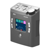
2-8 User Instructions MKP-4, BKP-4, WKP-4, TKP-4, and MKP12 Keypanels
CONNECTIONS
Mic Connector
To connect a panel microphone, such as the RTS model MCP90, screw the microphone into the
Mic connector on the front panel of the keypanel.
NOTE
For Mic connector specifications, see “SPECIFICATIONS” in Section 1.
Headset Connector
The Headset connector accepts a monaural, dynamic-microphone headset (headphones and
microphone). If you use a headset, make sure DIP switch 4 is set to the Open position.
Alternatively, headphones can be connected when a panel microphone is used for talkback. Or, a
handheld dynamic microphone can be connected when a speaker is used for listening. If you use
either of these special configurations, make sure DIP switch 4 is set to the Close position.
NOTE
For Headset connector specifications, see “SPECIFICATIONS” in Section 1.
Connection To Intercom System
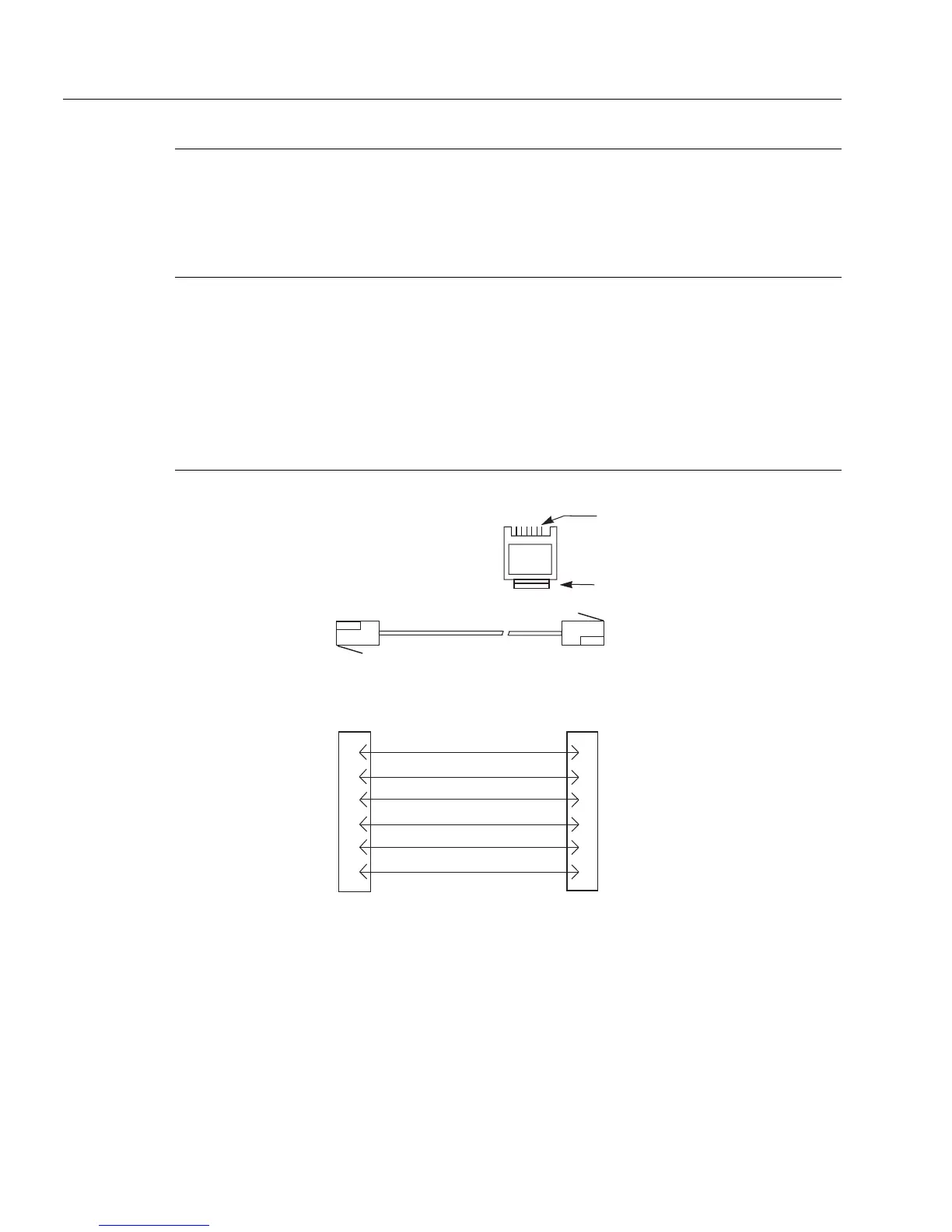
Figure 2.2
RJ12 Intercom cable wiring diagram
3 TWISTED PAIR TELEPHONE CABLE
1
2
3
4
5
6
DATA -
1
2
3
4
5
6
AUDIO FROM MATRIX +
AUDIO TO MATRIX -
DATA +
123456
CONTACTS
LATCH
RJ12 MODULAR PLUG
AMP 5-555042-3 or equivalent
(View from cable entrance)
Use AMP Chordal
Crimp Tool
231648-1
or equivalent
PAIR 1: AUDIO TO MATRIX
PAIR 2: AUDIO FROM MATRIX
PAIR 3: DATA
AUDIO FROM MATRIX -
AUDIO TO MATRIX +