2-9
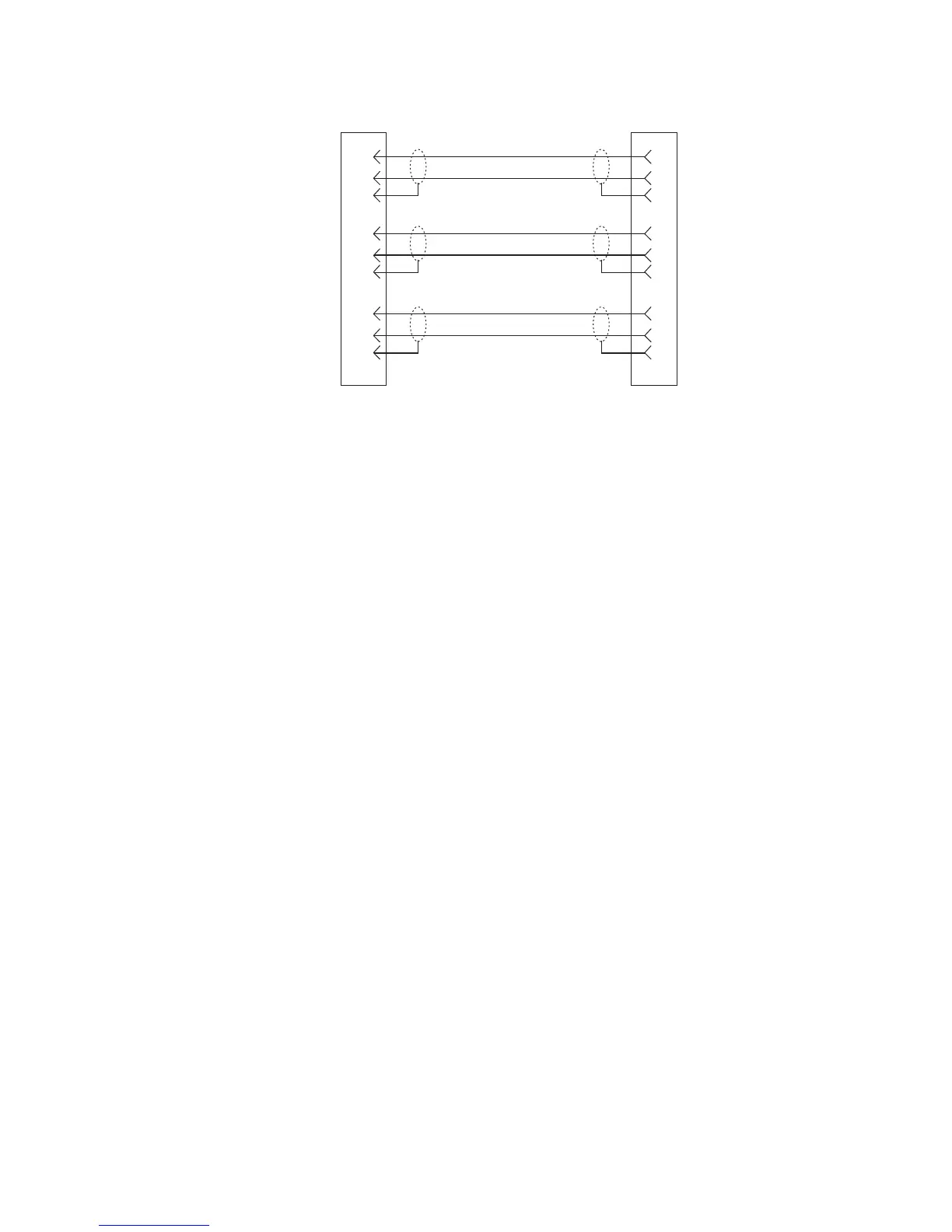
Figure 2.3
9-pin Intercom cable wiring diagram
Important!
Shield connections at the keypanel end are optional and may cause ground loops if used.
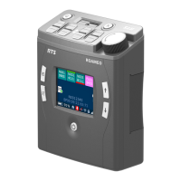
BKP-4 Connection
Use a standard RTS intercom cable. Either a 9-pin or RJ12 type can be used. Refer to Figure 2.2
or Figure 2.3. Plug one end of the cable into the appropriate Frame connector on the back panel of
the keypanel. Plug the other end into the appropriate port of the intercom system. (This will be the
port number that you designated previously when setting the Address switch.)
NOTES
• Keypanels may be connected while the intercom system is running.
• The 9-pin intercom cables for use with an ADAM CS frame must use special connectors at the
intercom matrix end as described in Figure.
DE-9P (MALE)
TO KEYPANEL
DE-9S (FEMALE)
TO INTERCOM SYSTEM*
CABLE TYPE:
BELDEN 8777
1
2
6
4
5
9
7
8
3
1
2
6
4
5
9
7
8
3
DATA
AUDIO TO MATRIX
AUDIO FROM MATRIX
+
-
+
-
-
+
When connecting to an ADAM CS back panel, use
only low-profile cable connectors such as AMP
Part No. 747516-3 (Telex Part No. 59926-678)
IMPORTANT!
*