2. RuggedBackbone™ Modules
RuggedCom® RuggedBackbone™ 10 RX5000 Installation Guide Rev 107
2.2. Control Module
The Control Module (CM) is the central processing unit of the RuggedBackbone™ chassis. The
ROX™ operating system running on the CM controls and coordinates the functions of all modules
installed in the system. The Control Module is installed in the CM slot of the chassis, as shown in
Figure 2.1, “Chassis Slot Assignment”.
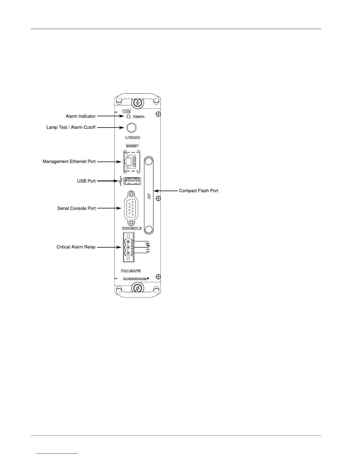
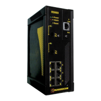
Figure 2.2. Control Module
The CM is equipped with an RS232 serial console port for initial management functions, and a locally
connected 10/100Base-T Ethernet port for system management out of band from the switch fabric.
Other CM features include:
• Alarm Indicator LED, which indicates system alarm status.
• Removable 1GB Compact Flash (CF) card, which contains active and fallback installations of the
ROX™ operating system, the configuration database, and other system data.
• Critical Alarm Relay, activated by the operating system to indicate a critical alarm.
• Lamp Test / Alarm Cutoff button.
• Utility USB port (as yet unused).
For detailed instructions on connecting to the ports on the CM, see the following: