3. Installation
RuggedCom® RuggedBackbone™ 24 RX5000 Installation Guide Rev 107
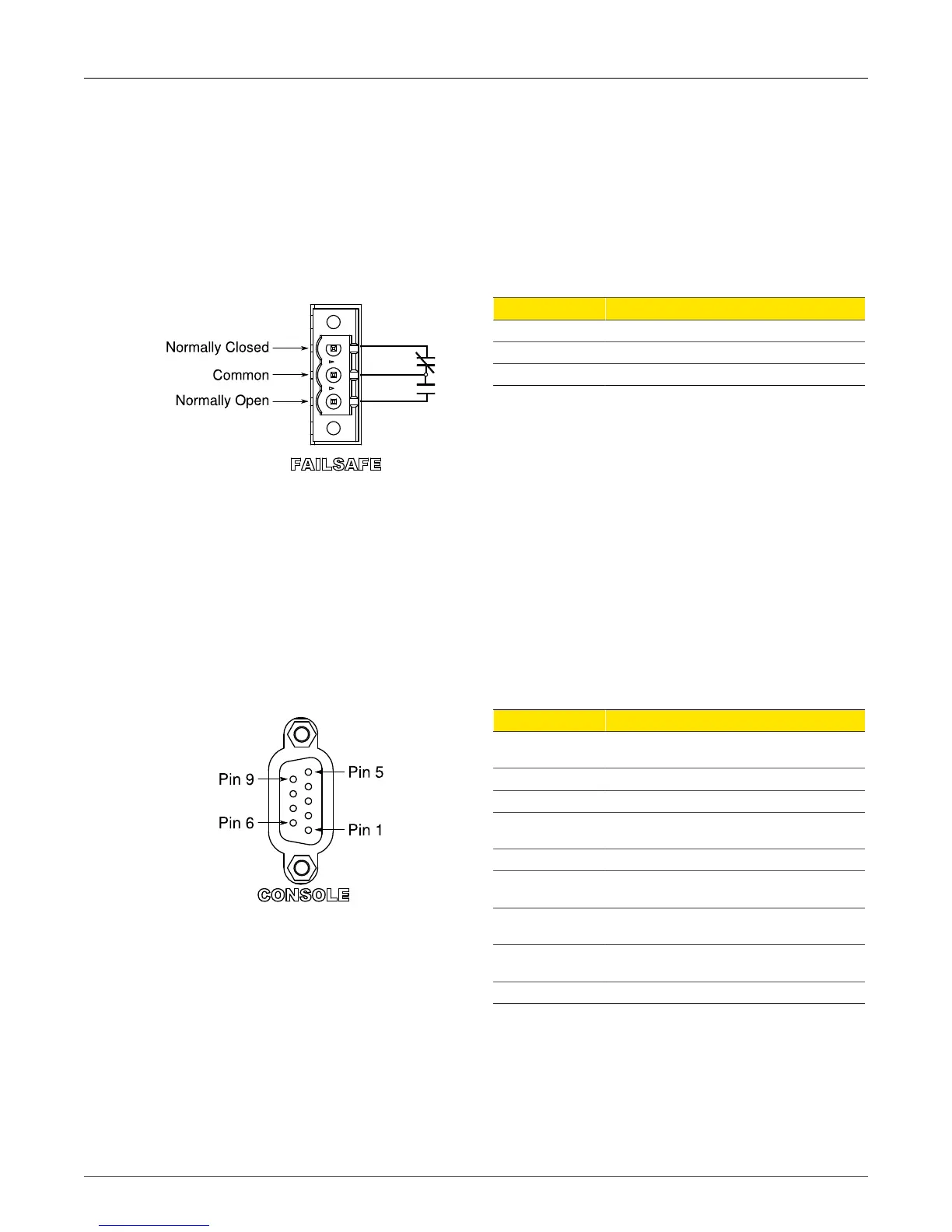
3.3. Critical Alarm Relay
The Critical Alarm output relay signals critical error conditions that may occur on the
RuggedBackbone™ RX5000. The contacts are energized upon power-up of the unit and remain
energized unless a critical alarm condition is detected. Relay connections are shown in the Critical
Alarm Relay Connection diagram. Control of the relay output can be configured via the ROX™ user
interface.
A common application for this output is to signal an alarm in case of a power failure.
Figure 3.16. Critical Alarm Relay Connection
Pin Function
NC Normally Closed
Common Ground
NO Normally Open
Table 3.2. RX5000 Critical Alarm Relay Connector Pinout
3.4. Serial Console Ports
The serial console port on the CM provides access to the boot-time control and configuration menu
interface. Both the CM serial console port and the one on the front panel of the RX5000 chassis
provide a console interface to the ROX™ operating system.
The serial ports implement RS232 DCE on a female DB9 connector. Serial settings are: 57600 bps,
8 bits, No parity, 1 stop bit. The pin assignment of both console ports is given in the Table 3.3, “Serial
Console Pinout” table.
Figure 3.17. Serial Console Port
Pin Function
1
DCD (DCD, DTR, and DSR
are looped back internally)
2 RX
3 TX
4
DTR (DCD, DTR, and DSR
are looped back internally)
5 GND
6
DSR (DCD, DTR, and DSR
looped back internally)
7
RTS (RTS and CTS are
looped back internally)
8
CTS (RTS and CTS are
looped back internally)
9 NC
Table 3.3. Serial Console Pinout