2. RuggedBackbone™ Modules
RuggedCom® RuggedBackbone™ 11 RX5000 Installation Guide Rev 107
• Serial Console: Section 3.4, “Serial Console Ports”
• Management Ethernet Interface: Section 3.5, “Copper Ethernet Ports”
• Critical Alarm (Failsafe) Relay Interface: Section 3.3, “Critical Alarm Relay”
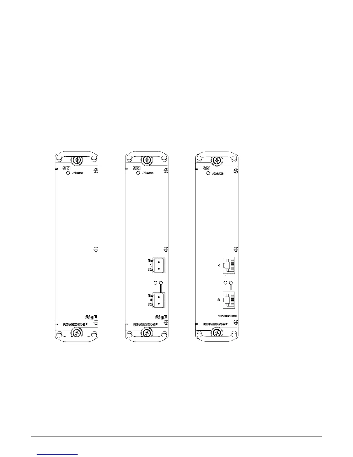
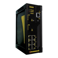
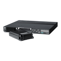
2.3. Switch Module
The Switch Module (SM) is the Ethernet switch fabric central to the RuggedBackbone™ RX5000.
It provides one Gbps of bandwidth to each installed Line Module and two 1Gbps ports to (optional)
connectors on its own faceplate. The Switch Module is installed in the SM slot of the chassis, as
shown in Figure 2.1, “Chassis Slot Assignment”.
Switch Modules can be ordered as separate components with copper, LC fiber, or with no Ethernet
ports. Refer to the RuggedBackbone™ RX5000 data sheet for complete ordering details.
Figure 2.3. Switch
Module - No Ports
Figure 2.4. Switch
Module - Fiber (LC)
Figure 2.5. Switch
Module - Copper