28
COMPILER TECO/ATI ENDORSEDDATE
01.08.2003
REG. CODE
1-5302-620
MODEL N°
50902
DATE OF ISSUE
08-03
REVISION 00
XI
40
41
42
43
5 kgm (49 Nm)
RD210 RD 211 RD270 RD278
A B
RD210 RD 211 0,25
RD270 RD278 0,28
RD210 RD 211 225 ÷ 235
RD270 RD278 220 ÷ 230
Engine
Engine
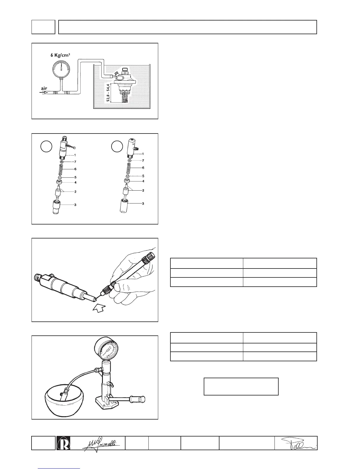
Testing air tightness
Feed pressurized air at 6 kg/cm² into the fuel sullpy union and
completely immerse the pump in oil or diesel fuel for about 20 ÷ 30
seconds (fig.40); check that no air bubbles are released.
N.B.: Tightness can be checked by compressing the springs to
52.8 ÷ 54.4 mm, which corresponds to the bottom dead centre
working position of the pump.
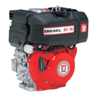
Injector checking and setting
1.Clean out nozzle holes with a thin piece of wire (fig. 42) of the
same size as that of the nozzle holes indicated on the table:
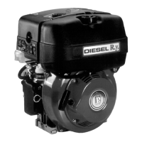
2.Set up injector on a test bench (tool cod. 00365R0430).
3. Unscrew injector lock coupling (No 3 fig. 41) or nozzle ring nut and
insert adjustment shim (7, fig. 41) until the pressure indicated in the
table hereunder is reached on the pressure gauge while pumping.
4.Tighten the nozzle ring nut (No 3 fig. 41) at:
5.When setting is complete, while still at the test bench, run
pumping elements a few times and check the amount of diesel
that passes through the upper leak-off of the injector (fig. 43).
Ø holes mm
Setting kg/cm
2
INJECTION EQUIPMENT
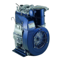
Injectors (fig. 41)
The engines can be equipped with three different types of injectors.
Type A injector for RD 210-211
1.Body - 2.Nozzle - 3.Ring nut - 4.Plate - 5.Rod - 6.Spring -
7.Adjustment shim.
Type B injector for RD 270-278
1.Body - 2.Nozzle - 3.Ring nut - 4.Plate - 5.Rod - 6.Spring -
7.Adjustment shim.