32
COMPILER TECO/ATI ENDORSEDDATE
01.08.2003
REG. CODE
1-5302-620
MODEL N°
50902
DATE OF ISSUE
08-03
REVISION 00
49
50
51
52
XII ENGINE ASSEMBLY
Notice: These instructions are valid for engines up-dated
prior to the publication of this manual. Any modifications
must be checked on the technical circulars.
Before assembling the engine carefully clean all parts
and dry them with compressed air. Lubricate moving parts
to prevent seizing when starting up. Replace the gaskets
with new ones each time the engine is assembled.
Use torque wrenches to ensure that the correct tightening
torques are applied.
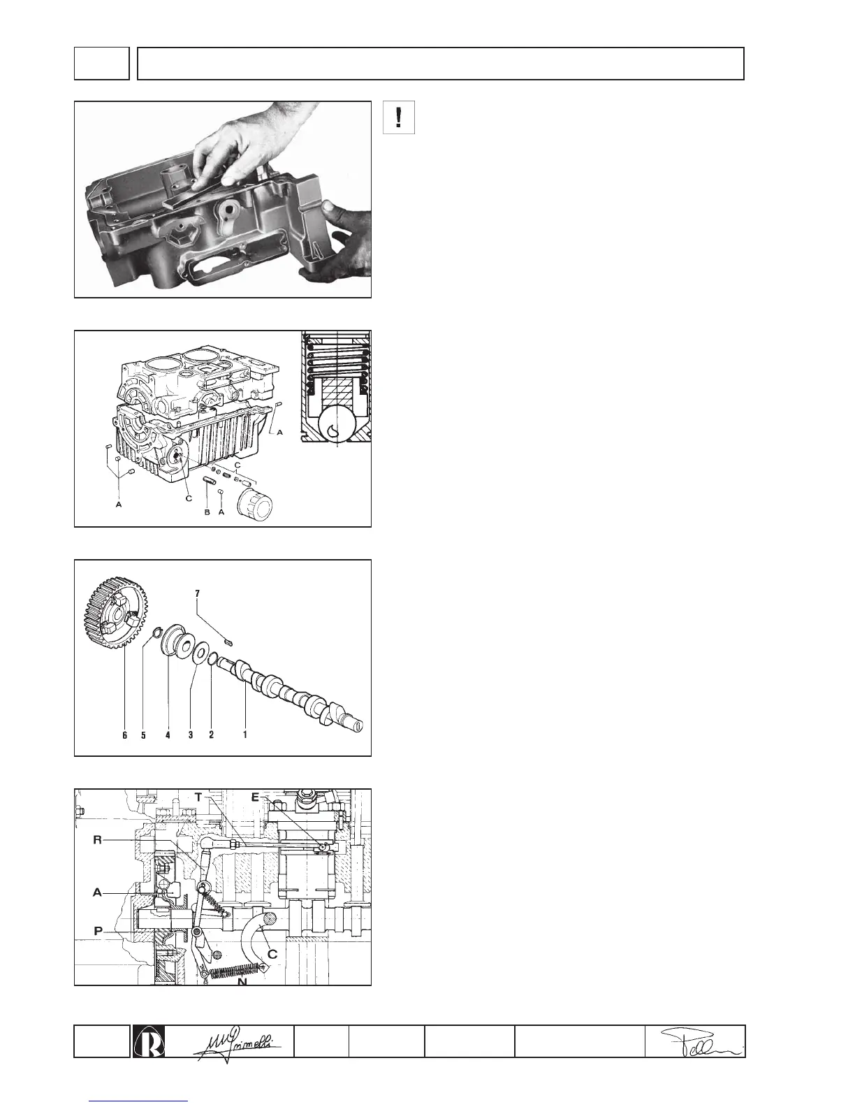
Preparation of crankcase
Clean support faces and remove seal residue and dirt with a
copper plate or a fine emery stone to avoid damage to the contact
surfaces (fig. 49).
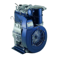
Lower crankcase (fig. 50)
1.Insert plugs (A) into relative seats.
2.Screw in oil filter cartridge connection (B). The connection
should protude 11 to 13 mm. from the crankcase.
3.Insert complete oil pressure register valve into its seat (C).
Make sure the seat of the valve ball in the casing is free of dirt or
scores which could jeopardize the pressure seal.
4.Insert cylinder studs and centering pins.
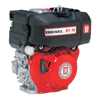
Camshaft preparation
To prepare the camshaft unit (fig. 51) proceed as follows:
1.Insert shim adjustment washer (No 3) and governor plate
(No 4) on camshaft.
2.Fit snap ring (No 5) and tab (No 7) into respective housings.
3.Heat gear (No 6) complete with masses and insert onto
camshaft making sure it rests against the locking snap ring.
4.Insert governor plate locking ring (No 2).
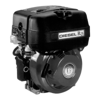
The speed governor is of the centrifugal mass type splined
directly onto the ends of the camshaft gear (fig. 52).
Masses (A), pushed outwards by the centrifugal force, shift mobile
plate (P) axially. Said plate actions lever (R) connected to injection
pump rack bar (E) by means of tie rod (T).
A spring (N) placed under tension by the accelerator (C), contrasts
the action of the centrifugal force of the governor.
The balance between the two forces keeps the revolutions
practically constant when load is changed.
For pre-load adjustment of the speed governor see paragraph on
page 40 "Injection pump tie rod connection".