38
COMPILER TECO/ATI ENDORSEDDATE
01.08.2003
REG. CODE
1-5302-620
MODEL N°
50902
DATE OF ISSUE
08-03
REVISION 00
72
73
74
75
XIII
0,25 ÷ 0,35 mm
0,9 ÷ 1,1 1,8
RD210 RD 211 2,25 ÷ 2,75
RD270 RD278 3,75 ÷ 4,25
mm
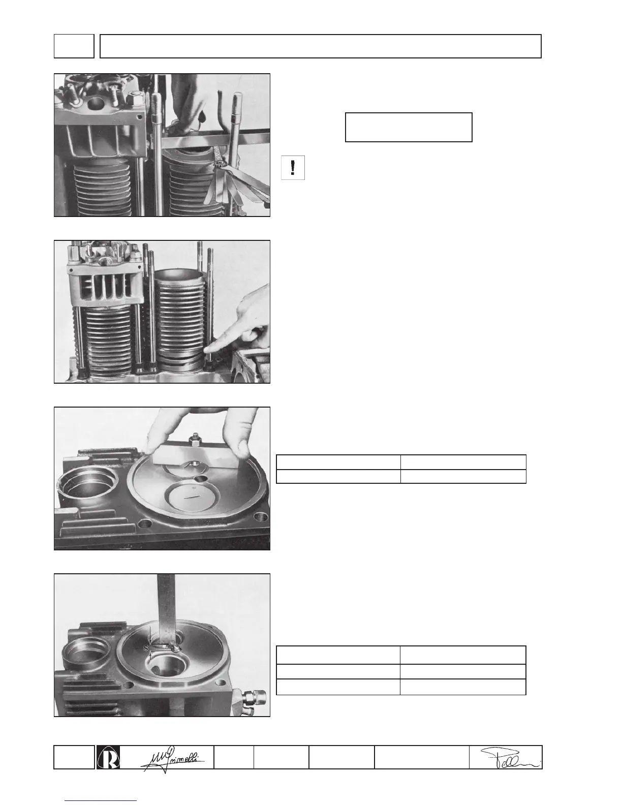
In order to carry out this operation correctly, make the
check with the cylinder pressed well down on its
crankcase (fig. 72).
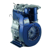
The clearance is adjusted by means of shims inserted between the
lower face of the cylinder and crankcase (fig. 73).
Shim dimensions: 0.1 to 0.2 mm
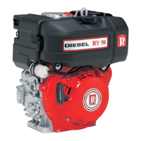
Cylinder height adjustement
Between the top face of the cylinder and the piston at top dead
center, there must be a clearance of:
Checking valve head face depth
When replacing valves check that the clearance from the top of the
head to the face (fig. 74) is of:
For different values see on pages 18-19.
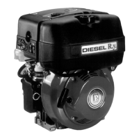
Checking injector protrusion
Before mounting the heads on the cylinders, insert injectors in their
housings and after having secured them temporarily, check
protusion of nozzles from head surface (fig. 75).
Protusion S should be:
Fitting mm Max. wear mm
ENGINE ASSEMBLY
Engine