18
COMPILER TECO/ATI ENDORSEDDATE
01.08.2003
REG. CODE
1-5302-620
MODEL N°
50902
DATE OF ISSUE
08-03
REVISION 00
IX
5
6
7
8
7,000 ÷ 7,010
7,0797,000
9,020 ÷ 9,030
9,040 ÷ 9,055
9,020
9,040
9,100
9,130
RD210
RD211
RD270
RD278
RD210
RD211
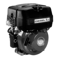
40 x 12 mm
A x B
RD270
RD278
A x B
7 mm 38 x 12 mm 7 mm
38 x 12 mm 9 mm 38 x 12 mm 9 mm
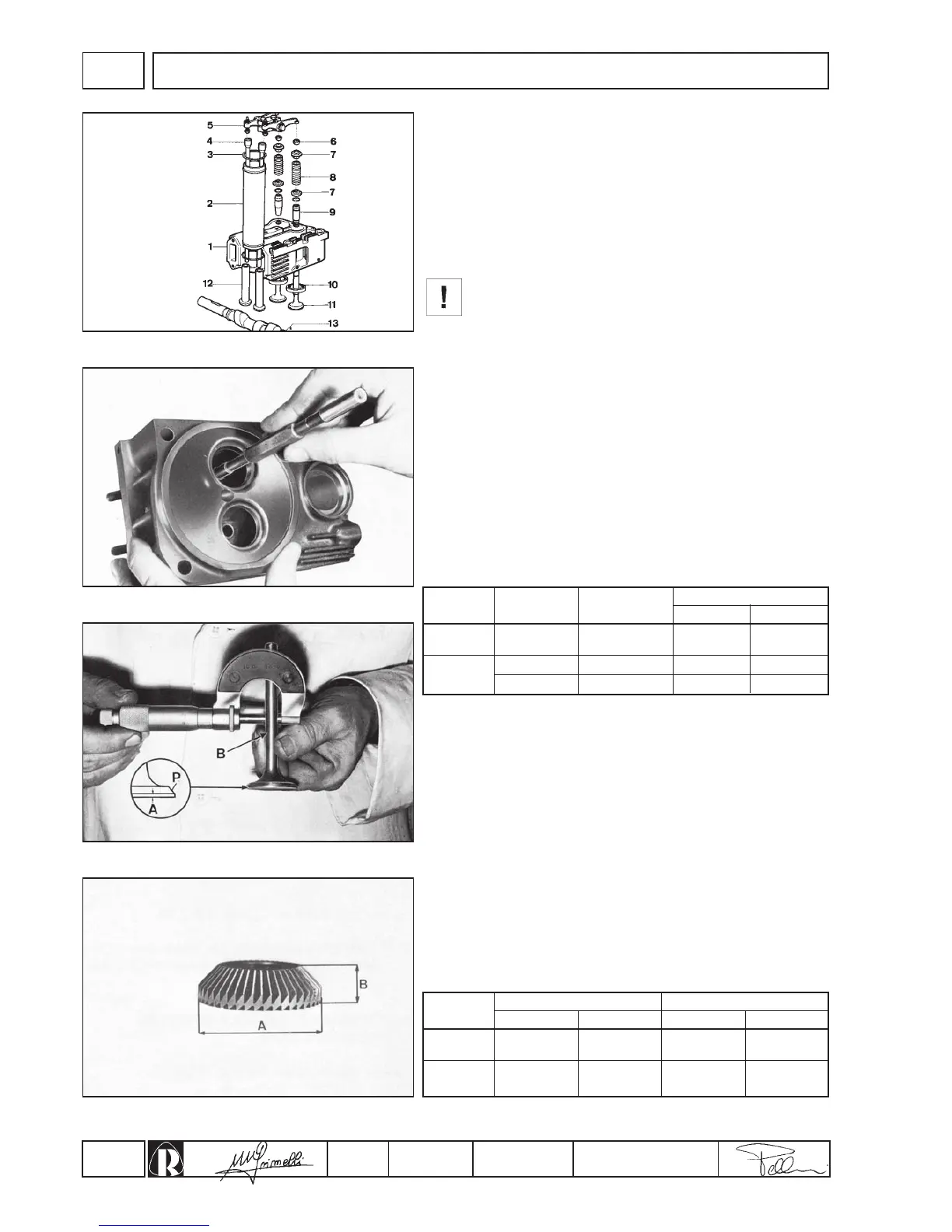
Cylinder heads
Details of fig. 5:
1. Cylinder head - 2. Pipe - 3. O-Ring - 4. Rockerarms - 5. Rockers -
6. Cotters - 7. Plates - 8. Springs - 9. Guides - 10. Seats - 11. Valves
- 12. Tappets - 13. Camshaft.
The heads are of aluminium with inserted guides and valve seats in
cast iron. Make sure there are no cracks or imperfections. Should it
be so, replace according to the instructions given in the spare parts
catalogue.
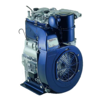
Never remove head while still hot in order to avoid
deformation.
Fitting of new guides always requires grinding of the valve seats
(see page 19).
Valve guides with an external diameter increased by 0.10 mm are
available.
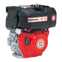
If the inlet clearance between valve and guide is lower than 0.08
mm and the outlet clearance is lower than, 0.10 mm, the wear on B
is less than 0.03 mm and A is more than 0.05 mm, recondition the
valve by grinding face P to 45° (fig. 7).
As a result of prolonged engine operation, the hammering of the
valves on their seats at high temperature causes the face of the
seats to harden and hand grinding is made difficult. It is thus
necessary to remove the hardened surface with a 45° cutter
mounted on a valve seat grinding tool (fig. 8). Final fitting can then
be carried out manually with the cutters listed below.
Cut dimensions for valve seats
CHECKS AND OVERHAUL
Valves - Guides - Seats
Clean the valves with a wire brush and renew them if the valve
heads are deformed, cracked or worn.
Check clearance between valve and guide with a micrometer on
stem B (fig. 7) and with a go/no go gauge as shown in fig. 6 (tool
cod. 00365R0450, 00365R0400, 00365R0410).
Change the guide if the maximum gauge diameter passes through
it, as it has passed the maximum permissible wear.
After having fitted the new guide, check exact diameter using the
“go” end of the gauge and if necessary grind it to the dimensions
indicated in the table using the adjustable grinder (tool cod.
00365R0850, 00365R0860).
Engine Guide
Ø Guide
mm
Ø Gauge mm
go no go
Inlet
Outlet
Inlet
Outlet
Engine
Inlet
Ø guide
Outlet
Ø guide