23
COMPILER TECO/ATI ENDORSEDDATE
01.08.2003
REG. CODE
1-5302-620
MODEL N°
50902
DATE OF ISSUE
08-03
REVISION 00
X
23
24
25
26
A
B
-0,50 mm
44,505
÷
44,515
44,494
÷
44,510
-0,25 mm
44,755
÷
44,765
44,744
÷
44,760
STD mm
45,005
÷
45,015
44,994
÷
45,010
47,965 ÷ 47,985
48,965 ÷ 48,985
CHECKS AND OVERHAUL
Dimensions
Undersize bearing bushes are already available at the necessary
sizes without requiring any adjustment by boring.
Main bearing bushes with increased external diameters are also
available. Table indicates the crankcase boring values.
Crankshaft
Whenever the engine is dismantled, particularly for the replacement
of cylinders and pistons due to wear caused by the aspiration of
dust, it is good practice to check the condition of the crankshaft.
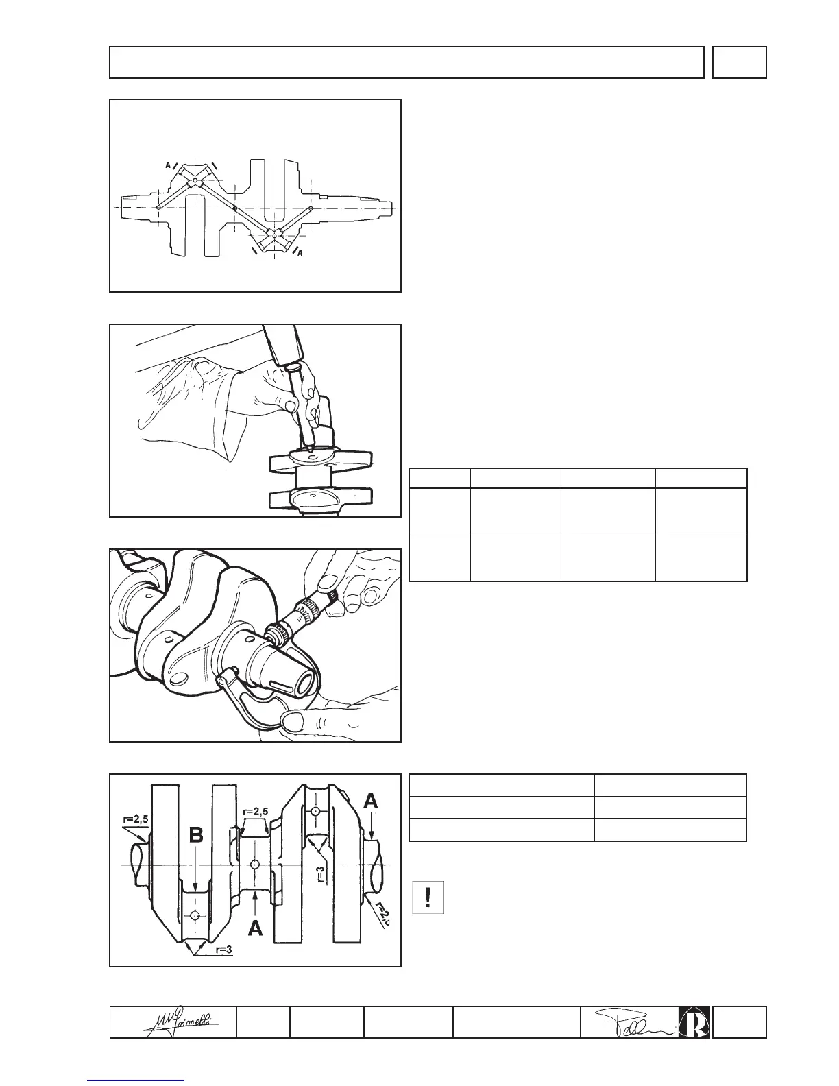
1.Remove the plugs “A” from the oil passages (fig.23).
2.Use an appropriately shaped steel punch to clean the inside of
the oil passages and the collection traps. If the deposits are
particularly resistant, immerse the whole crankshaft in petrol or
paraffin before proceeding with the operations.
3.When the oil passages and traps have been throughly cleaned,
close the openings with new plugs (fig.24).
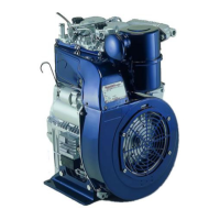
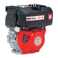
Checking crankshaft dimensions
Once the crankshaft has been thoroughly cleaned, use a
micrometer to check the wear and ovality of the main journals and
crank journals across two sections at right angles to each other
(fig.25).
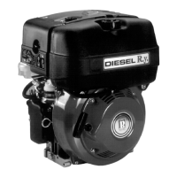
If wear exceeds 0.08 mm (fig.26) grind the crankshaft to the
dimensions shown in the table:
Bearing
Standard
+ 1 mm
Ø of brush housingmm
During grinding take care not to remove the shim
adjustment material from the main journal thrust face to
avoid changing the crankshaft end float; also ensure that
the grinding wheel radii are as specified in figure 26 so as
not to create crack initiation sections on the crankshaft.