26
COMPILER TECO/ATI ENDORSEDDATE
01.08.2003
REG. CODE
1-5302-620
MODEL N°
50902
DATE OF ISSUE
08-03
REVISION 00
XI
33
34
35
RD210 RD 211
RD270 RD278
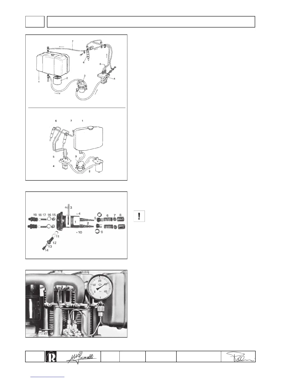
Fuel circuit
Feeding is carried out by a diaphram pump actuated by a camshaft
eccentric coupled to a cap.
See assembly on page 36 and consult spare parts catalogue for
replacement.
Details of fig. 33:
1.Tank - 2.Diesel filter - 3.Feeding pump - 4.Injection pump -
5.Injection pipes - 6.Injectors - 7.Diesel discharge pipe.
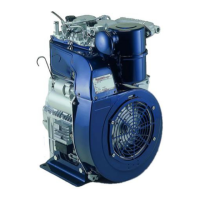
Injection pump
The injection pump is of the single casing type with two, constant
stroke, separate pumping elements. Details of fig. 34.
1.Pump casing - 2.Pumping element - 3.Rack bar - 4.Eccentric
dowel - 5.Adjusting bushing - 6.Spring - 7.Lower plate - 8.Tappet -
9.Upper plate - 10.Locking pin - 11.13.18.Gaskets - 12.Diesel intake
connection - 14.Diesel exhaust screw - 15.Delivery valve -16.O-ring -
17.Valve spring - 19.Delivery connection.
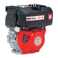
Checking injection pump
Before dismantling injection pump check pressure seal of the
pumping unit, cylinder and valve as follows:
1.Connect a pressure gauge graded up to 600 kg/cm² (fig. 35) to
the diesel delivery pipe.
2.Set the rack bar in a half way position.
3.Rotate flywheel showly until the pumping element has
completed a compression stroke.
If the test is carried out on the bench, take care that the
pumping element does not strike the delivery valve while
pumping.
4.Take the pressure gauge reading. If the reading is less than
300 kg/cm² , the complete pumping unit must be replaced.
During the test, the reading on the gauge will show a
progressive pressure increase to a maximum value and will
then fall suddenly and stop at a lower pressure.
Replace valve if the fall in pressure exceeds 50 kg/cm² and
continues to fall slowly.
Injection pump setting
Register eccentric dowel to the maximum capacity of the pumping
elements (q, fig. 39).
INJECTION EQUIPMENT