11
Rear View Safety, 1797 Atlantic Ave., Brooklyn NY 11233
800.764.1028 sales@rearviewsafety.com
www.rearviewsafety.com
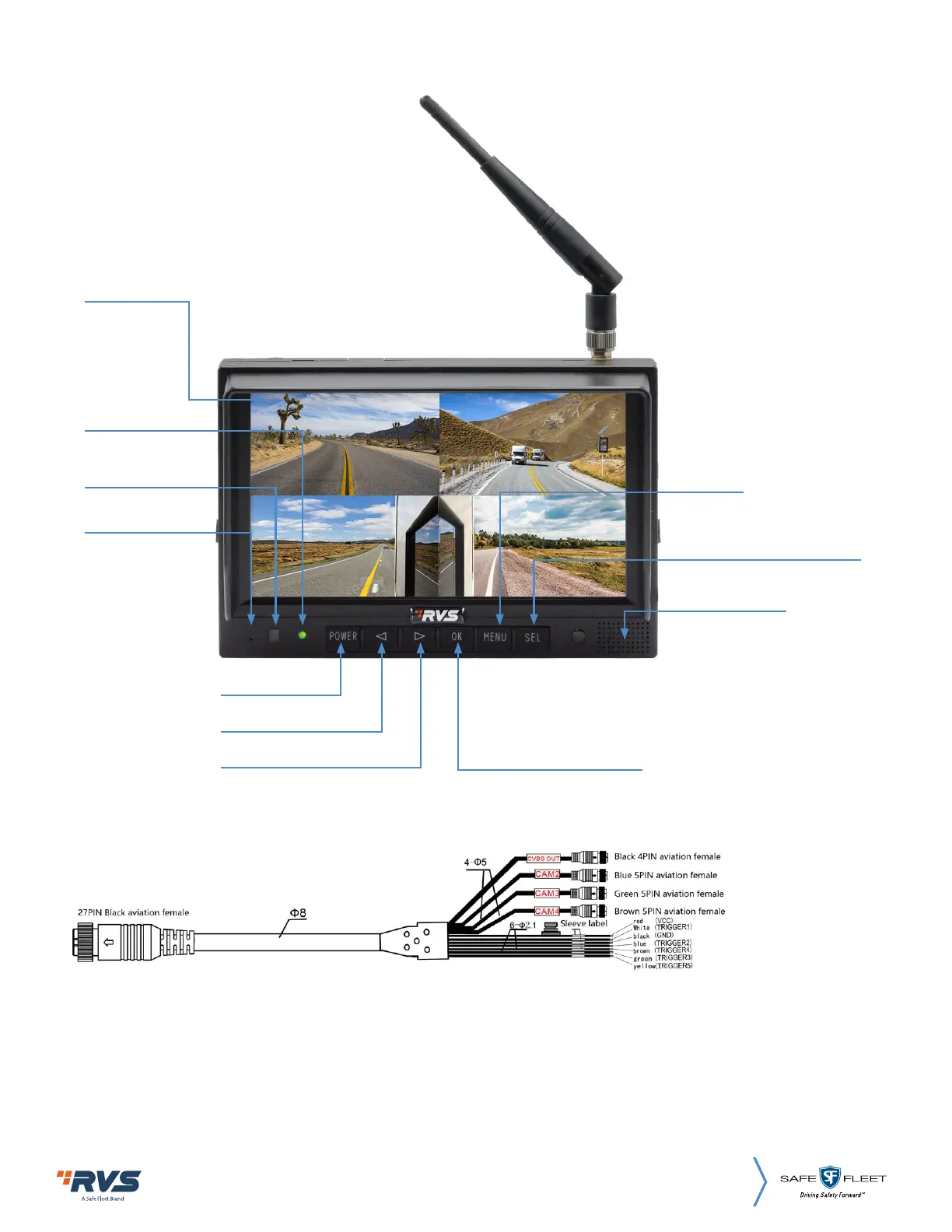
5. PARTS IDENTIFICATION
Digital Color
LCD Screen
Power Indicator
Remote Control
Sensor
Light Sensor
Power Switch
Loudspeaker
Single Split: The screen
will be enlarged.
Menu
Volume Up
Volume Down
Press OK button to switch to
split mode.
Press OK button under Menu
to enter Menu options.
5. CONNECTIONS
1. Black 4P female for CVBS outputs.
2. Blue 5P male for Camera 2.
3. Green 5P male for Camera 3.
4. Brown 5P male for Camera 4.
5. Single red wire to power wire of DC: 10~32V.
6. Single black wire to GND.
7. Single white wire to trigger Camera 1.
8. Single blue wire to trigger Camera 2.
9. Single green wire to trigger Camera 3.
10. Single brown wire to trigger Camera 4.
11. The yellow wire to trigger reverse.
Active high (10V to 32V).
 Loading...