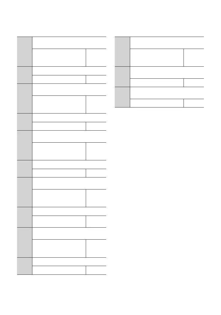
102
F6.42
AI1 curve inexion point 2 input
corresponcling setting
-200.0% ~ 200.0%
Note: range associated
with F6.00
60.0%
F6.43
AI1 curve max input
【F6.41】~ 10.00 10.00
F6.44
AI1 curve max input corresponding
setting
-200.0% ~ 200.0%
Note: range associated
with F6.00
100.0%
F6.45
AI2 curve min input
0.00 ~【F6.39】 0.00
F6.46
AI2 curve min input corresponding
setting
-200.0% ~ 200.0%
Note: range associated
with F6.00
0.0%
F6.47
AI2 curve inexion point 1 input
【F6.45】~【F6.49】 3.00
F6.48
AI2 curve inexion point 1 input
corresponding setting
-200.0% ~ 200.0%
Note: range associated
with F6.00
30.0%
F6.49
【F6.47】~【F6.51】
AI2 curve inexion point 2
input
6.00
F6.50
AI2 curve inexion point 2 input
corresponding setting
-200.0% ~ 200.0%
Note: range associated
with F6.00
60.0%
F6.51
AI2 curve max input
【F6.49】~ 10.00 6.00
For details, see the functional description of
No. 57 (AI1 input over limit) in the function
code F7.18 ~ F7.21.
4.2 Detailed Function Description
F6.52
AI2 curve max input corresponding
setting
-200.0% ~ 200.0%
Note: range associated
with F6.00
100.0%
F6.53
AI1 input voltage protection upper
limit
【6.54】~ 10.00V 6.80
F6.54
AI1 input voltage protection lower
limit
0.00V ~【6.53】 3.10