Revised 10/02/2012 1.11
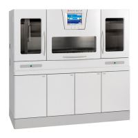
Transfer System (Figure 1-M)
The Transfer System performs the automated process
of transferring baskets from the Loading Station to the
Microwave and Vacuum Stations, and ultimately to the
Unloading Station. The Transfer System is comprised of a
motor-driven transfer arm
..23
.. that provides for move-
ment in the X (horizontal) and Z (vertical) axes.
Figure 1-M
When the instrument is not processing specimens, the
transfer arm can be moved manually.
A drip pan
..23a
.. associated with the transfer arm
prevents reagent from dripping onto the top panel in the
instrument when a basket is transferred between stations.
A disposal tray liner
..23b
.. receives reagent drips. A
rotational drive associated with the drip pan automatically
retracts the drip pan to allow the transfer arm to raise or
lower a basket. The drip pan is returned to its location
beneath the basket while traveling horizontally between
stations.
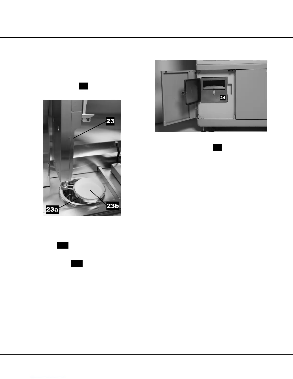
Fume Control System (Figure 1-N)
Figure 1-N
The Fume Control System ..
24
..
is comprised essential-
ly of a hood, activated carbon absorption filter, and
exhaust fan. The Fume Control System is accessed
through a door in the cabinet front (see “Cabinet Front
(Figure 1-A)” on page 1.3 for details).
The Fume Control System hood serves to prevent
hazardous fumes from leaking to the outside of the
instrument. The system collects reagent fumes from inside
the instrument and passes them through an activated
carbon absorption filter to reduce fume emissions to
acceptable levels. The filtered air is then discharged to the
atmosphere. The fume control exhaust fan is active
whenever power is applied to the instrument. In the event
the fume control exhaust fan fails while the instrument is in
operation (processing is being performed), an audible
alarm sounds.
Additionally, a duct is provided on the instrument rear
panel to facilitate connection of the Fume Control System
to a facility exhaust system.
 Loading...