9
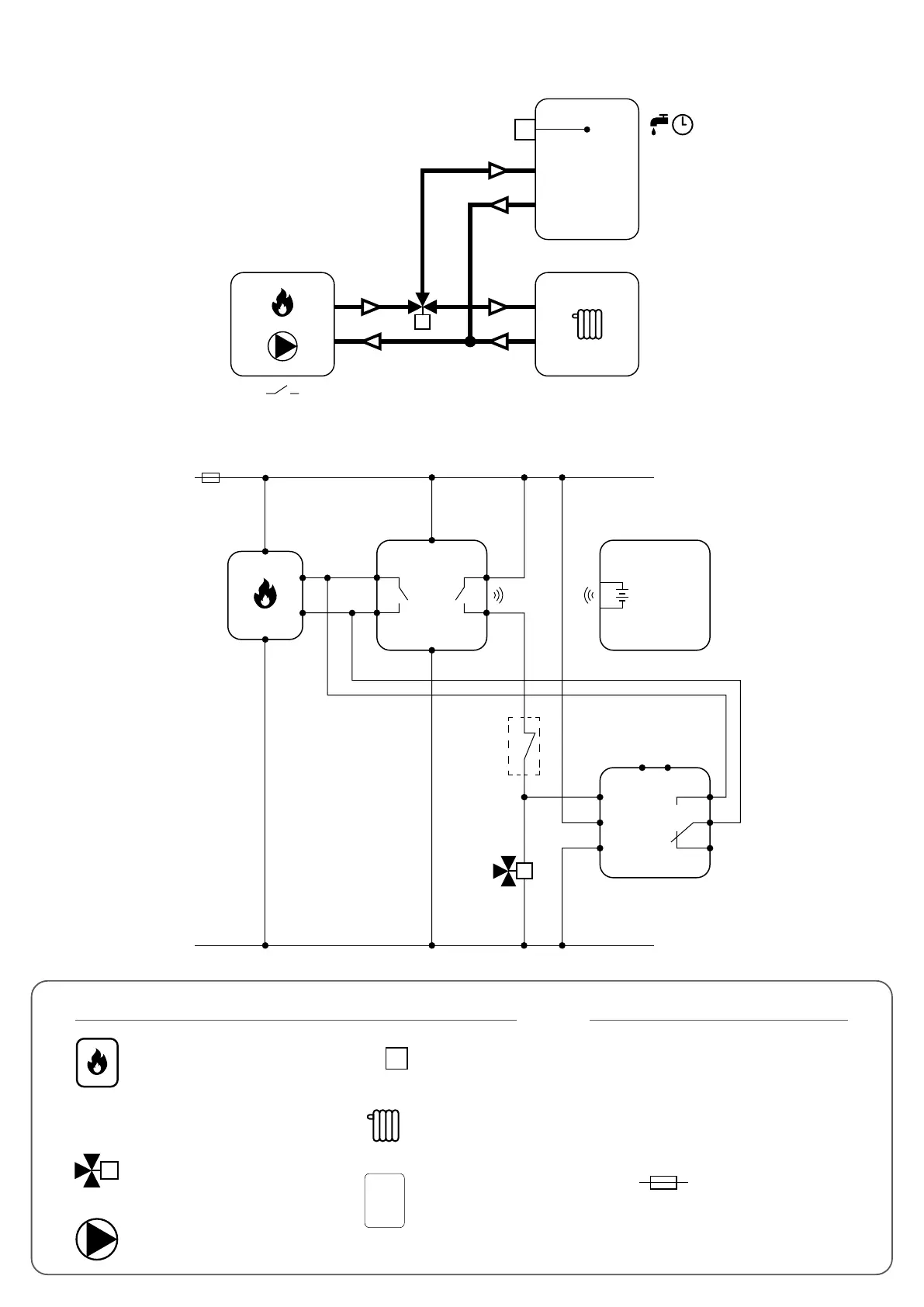
A - Boiler (radiator system) and hot water pump control
2.3.2 Wiring diagrams for single heating zone and hot water timer
M
ON / OFF
TAT10F
TIMER
Hydraulic diagram:
Electric diagram:
N
L
L
AC 230V
N
COMCOM
NONO
iT500RX
N
L
iT500TX
3V
2 x AA
M
RM-16A
NO
NO
COM
COM
AT10F
1
C
NC
SL
N
L
L, N - power supply 230V
NO, COM, NC - voltage-free output
SL - 230V AC voltage output
- fuse
Legend: Symbols explanation:
Changeover valve
DHW immersion
thermostat
Radiator heating
Hot water tank
Pump
Boiler - Boiler connection*
- Boiler’s contacts for ON/OFF
thermostat (according to the
boiler’s instructions)
M
TAT10F
BOILER CONNECTION *
(input)
DHW
DHW
CH
OUTPUT
AUX
OUTPUT