SAM4S ER-350 SERIES 5-1
5 Alignments and Adjustments
This chapter describes the methods for aligning and adjusting components in this ECR.
5-1 Printer Adjustments
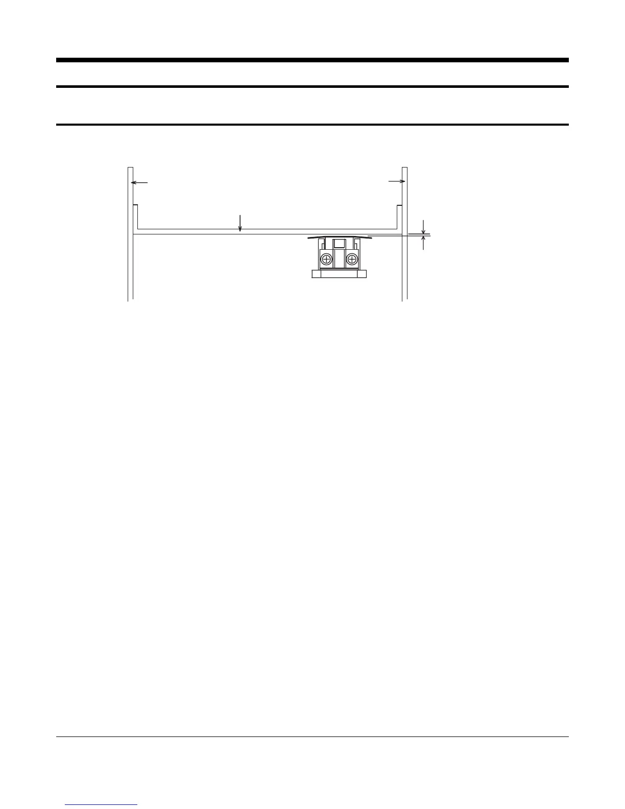
5-1-1 Head Gap Adjustment
Side Frame L Side Frame R
Platen
0.4~0.55m
Dot Head Unit
Figure 5-1 Head Gap Adjustment
1. Remove the Ad. Lever screw.
2. Rotate the Gear 1
st
Reduction to move Head to the left end of Platen Guide.
3. Insert Gap Gauge (thickness 0.5 mm)
Between Head and Platen. Adjust the gap while rotating the Shaft Head Guide.
Tolerance = 0.4 to 0.55 mm
4. Wind Ad. Lever screw again and move
Head to the center of the Platen Guide
5. Insert Gap Gauge (0.5 mm) and tighten the Shaft Head Guide.
Tolerance = 0.4 to 0.55 mm
6. Repeat steps 4 and 5 moving the Head to the right end of the Platen Guide.
7. Replace the Ad. Lever screw.