SAM4S ER-350 SERIES 4-1
4 Disassembly and Assembly
Caution :
· Before installation, be sure to turn off the power switch.
· Use gloves to protect your hand from being cut by the angle and the chassis.
· Connect all the cables correctly. When connecting or disconnecting the cables, be careful not to apply
stress to the cables. (It may cause disconnection)
· Be careful not to bind interface cables and AC power cord together.
4-1 Disassembling the Case Upper Block
4-1-1 Upper Case Disassembling
1. Lift off Printer Cover(A).(Page7-1)
2. Remove two screws (B5 and B1) on Upper Case and lift it up.(Page7-1)
3. Remove connectors from the red the white connectors on Main PCB.(Page7-1)
4. Remove Upper Case.
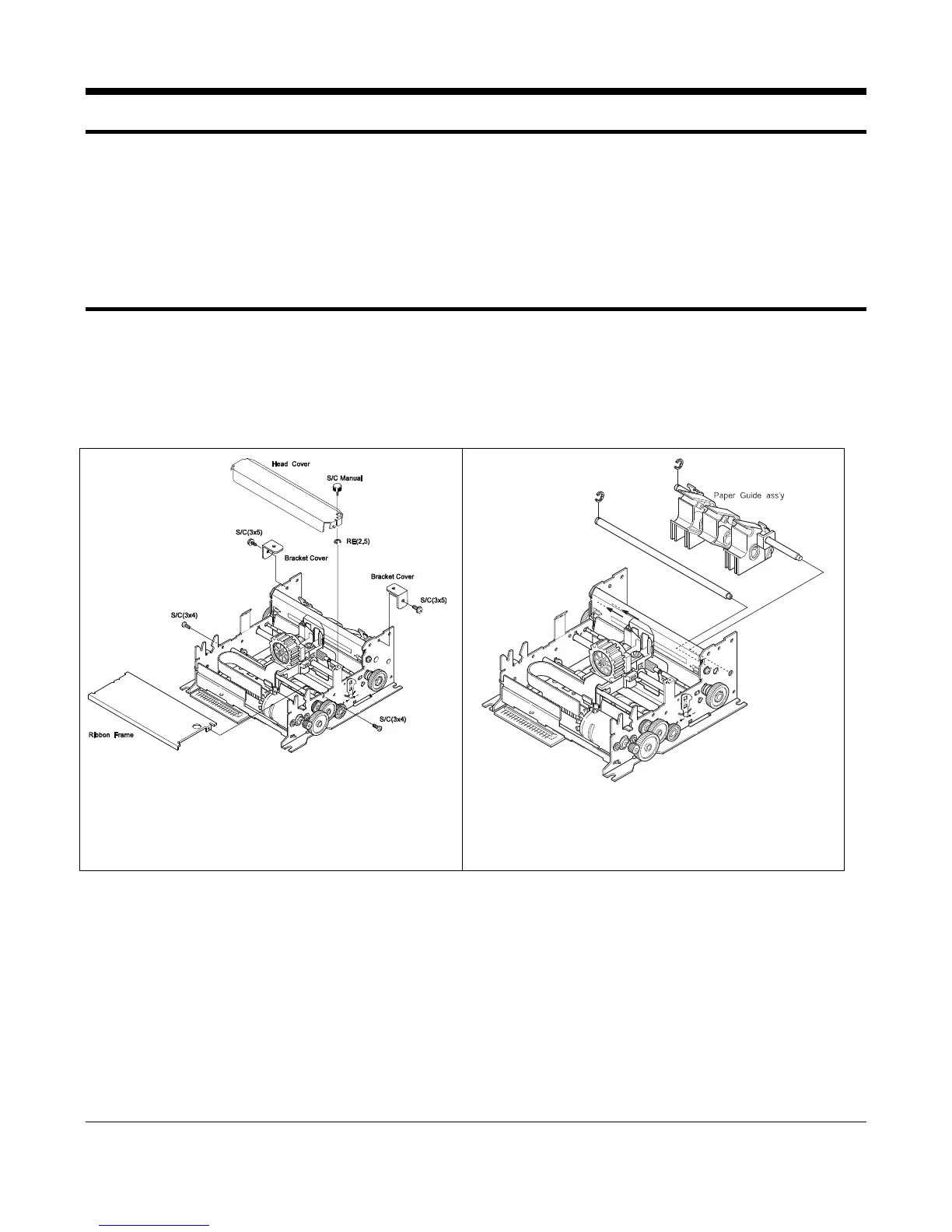
4-1-2 ERP-200N Printer Disassembling
Figure 4-1. Separating Head Cover
and Ribbon Frame
RE(4.0)
RE(5.0)
Shaft Paper Guide
B
B
A
A
Figure 4-2. Separating paper Guide Block
1. Remove 4 screws in the Frame Assembly to separate to the Head Cover and Ribbon Frame.(Figure4-1)
2. Separate the E-Ring (RE5.0) to separate the Shaft Paper Guide from the Frame Assembly. (Figure4-2)
3. Separate the E-Ring(RE4.0) Remove the screws to separate the Paper Guide Assembly from the Frame Assembly.
(Figure4-2)