7 Special Circuit Description
SAM4S ER-380M/F SERIES 7-5
7-3 Battery, RTC(Clock), Buzzer and Cash Drawer Circuits
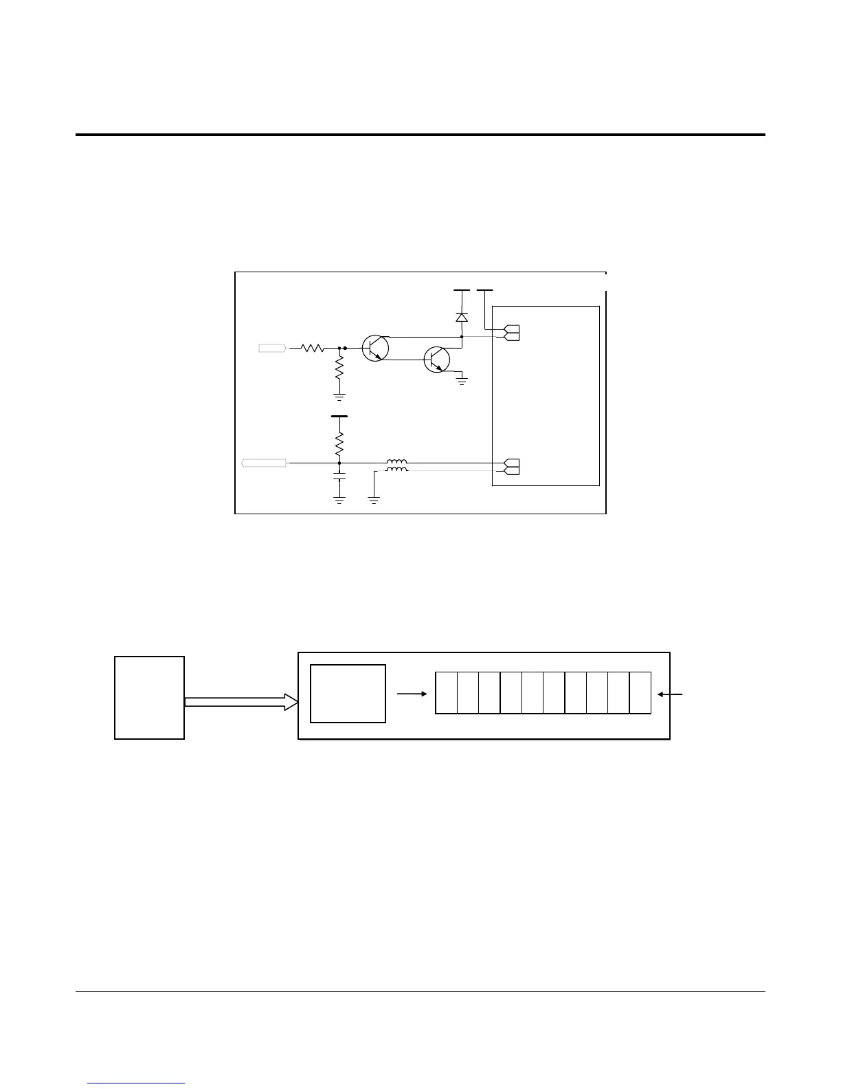
7-3-4 Cash Drawer Driving Circuit
The circuit is used for opening cash drawer and driven by the Q5(MMBT222A),Q1(KSD288-Y). When its state is high
level signal, Q5(MMBT222A) or Q1 (KSD288-Y) drive the solenoid to open the cash drawer. As an optional item, we
provide sensor switch (we call it a compulsory switch) which checks the drawer whether it is opened or not. This sensor
switch turns on for the drawer open condition, and turns off for the other.
Caution: Make sure that the Cash Drawer solenoid resistance is more than 20Ω
V144
C72
100nF
VCC
R5
10K
VDRV
DIODE-M4
D1
1
CN7:1
VDRV
3
CN7:3
R1
10K
R2
4.7K
1
2
3
KSD288
Q1
[ DRAW ER ]
SEN_DW RCOMP
L4
DRAW ER
L1
1
2
3
M M B T2222A
Q5
2
CN7:2
CON-BO X;4P ,2.5MM,ST(YH)
4
CN7:4
CON-BOX;4P ,2.5MM,ST(YH)
Figure 7-6 Cash Drawer Block Circuit
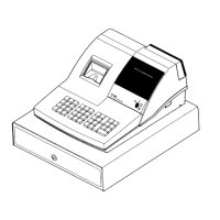
7-3-5 VFD Display Block Circuits
This uses 10digit Fluorescent Display and uses UCN5812AF (is located on the Front VFD PCB) for the driver. CPU
sends Display data to the driver repeatedly having given time interval in series and then Fluorescent Display is operated.
Figure 7-7 VFD Diagram & Waveform
10Digits
0 1 2 3 4 5 6 7 8 9
CPU
DRIVER
UCN5812
CLK, DATA, LATCH
STROBE
+30V,+5V,GND
Front & Rear VFD PBA