7 Special Circuit Descriptions
7-4 SAM4S ER-380M/F SERIES
7-3 Battery, RTC(Clock), Buzzer, Cash Drawer and VFD Circuits
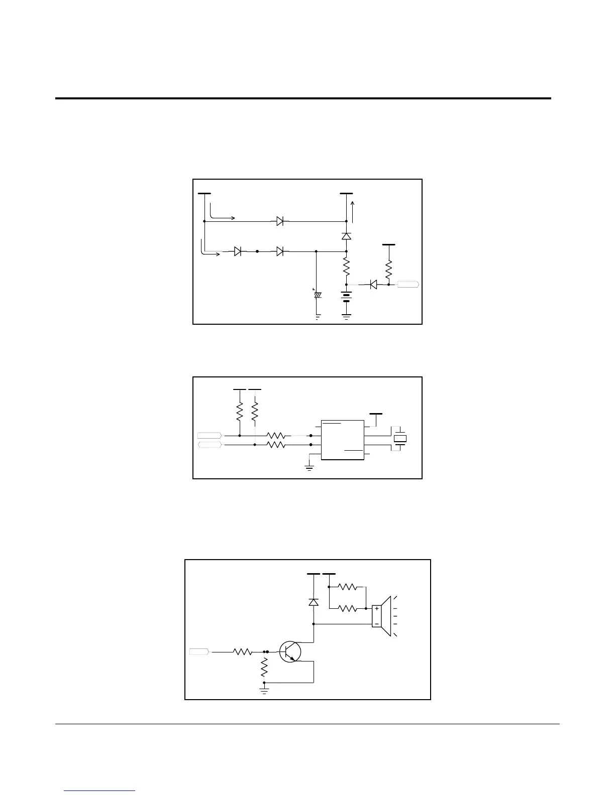
7-3-1 Battery Circuit
Battery Circuit supplies SRAMs and RTC (U14, RS5C372A) with voltage source and is used to drive clock and to save
data when the main Power is turned off. When the Power is turned on, VCC source(+5VDC) is supplied to SRAMs and
RTC through the D14(SK14), and the Battery is charged. When the Power is turned off, D14 is shut and the source
charged in the Battery is supplied to SRAM and RTC.
V67
ADC_BAT
DIODE-M4
D18
W hen Power On,
VBT Supply
VBT
VCC
100uF
C92
16V
10K
R 105
W hen Power On, Battery C harging
W hen Power Off,
VBT Supply
DIODE-SK14
D28
VCC
D13
DIODE-SK14
R 104
270
DIODE-SK14
D16
3.6V
BAT1
DIODE-SK14
D14
Figure 7-3 Battery Circuit
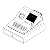
7-3-2 RTC(Clock) Circuit
This uses an Clock IC RS5C372A, is driven by the Battery when the main Power is turned off.
VCC
RTC_SDA
RTC_SCLK
R96100
VCC
R51
4.7K
R92100
VBT
3
SDA
6
OSCOUT
1
INTRB
8
VDD
2
SCL
4
VSS
7
OSCIN
5
INTRA
U14
R S5C 372A
32.768K H z
X2
V66
V65
R55
4.7K
Figure 7-4 RTC Circuit
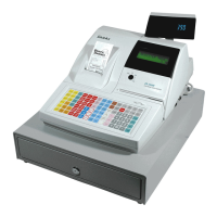
7-3-3 Buzzer Driving Circuit
The Buzzer is used to inform several kinds of states which occur under system operating and gives some information to
users by controlling the P8.0 pin of CPU. The frequency of buzzer is 2[KHz]
V69
R89
10K
AU1
BU ZZER
R86
4.7K
VDRVVCC
BU ZZER
D11
M M B D 6050LT1
R90
100
2
3
1
M M B T2222A
Q22
R91
100
Figure 7-5 Buzzer Circuit