Do you have a question about the Sam4s ER-380F and is the answer not in the manual?
Essential safety measures for servicing to prevent hazards and damage.
Guidelines for safe and effective servicing procedures.
Steps to prevent damage to ESD-sensitive components.
Overall technical specifications for the electronic cash register.
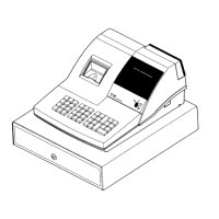
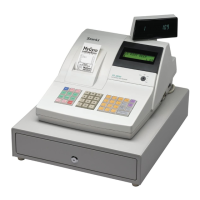
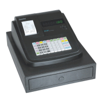
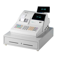
Details on the physical dimensions and feature locations of the ECR.
Technical details specific to the thermal printer.
Information regarding input voltage, current, and power consumption.
Details on serial (RS-232C) and other interface connections.
Overview of how the ECR connects to other system components.
Procedures for installing paper rolls, spools, and cables.
Guidance on using the mode switch and performing basic operations.
Step-by-step guide for removing the upper case assembly.
Detailed instructions for disassembling the lower case assembly.
Procedures for cleaning and routine maintenance tasks.
Pin assignments and functions for key semiconductor components.
Description of the system's power supply and voltage distribution.
Details on reset signaling and power failure detection.
Circuit descriptions for battery, clock, buzzer, drawer, and display.
Explanation of the keyboard scanning and input processing.
Description of the thermal printer's operation and control.
Diagnostic steps for power supply related issues.
Troubleshooting guide for general system operational failures.
Steps to diagnose and resolve issues with the VFD display.
Troubleshooting procedures for thermal printer malfunctions.
Guidance for diagnosing keyboard input failures.
Troubleshooting steps for drawer and spool motor issues.
Steps to resolve serial communication errors.
Exploded views and parts lists for the main cash register unit.
Exploded views and parts lists for the STM-210 printer.
Exploded views and parts lists for the keyboard assembly.
Exploded views and parts lists for the cash drawer assembly.
Layout and component list for the main printed circuit board.
Layout and component list for the printer's PCB.
Layout and component list for the power switch PCB.
Layout and component lists for front and rear displays.
Layout and component lists for fiscal memory and related components.
Layout and component lists for the interface connections.
System block diagram illustrating ER-380M components and connections.
System block diagram illustrating ER-380F components and connections.
Detailed pin connection information for various assemblies.
Schematics for the main printed circuit board.
Schematics for the power switch printed circuit board.
Schematics for the display printed circuit boards.
Schematics for the fiscal printed circuit board.
Schematics for the STM-210 printer's printed circuit board.
Schematics for the interface printed circuit boards.
| Type | Electronic Cash Register |
|---|---|
| Display | LCD |
| Number of Departments | 20 |
| Paper Width | 58mm |
| Cash Drawer | 1 |
| Operating Temperature | 0°C to 40°C |
| Printer | Thermal |
| Printer Type | Thermal Printer |
| Power Supply | AC 100V-240V |
| Operating Humidity | 10% - 90% RH |