SAMLEX AMERICA INC. | 115
have capability of providing potential free relay contact closure signal that could be fed to Inverter Charger to stop
charging or stop inverting. For this, the BMS will normally use miniature, Normally Open (1-Form-A), Open Drain Opto-
Isolated DC Solid-State Relay (SSR). The Solid-State Relay output terminals in the BMS are normally marked “+” (Drain
of Mosfet Switch) and “-” (Source of Mosfet Switch). Example of this type of relay is IXYS Part No. “CPC1002N” (60V,
700mA rating).
The following 2 types of signals are normally used by the BMS for on/off control of charging and inverting operation
of the Inverter-Charger:
• “Stop Charging” Signal: In case of (i) over voltage of individual cell / overall battery pack, or (ii) over
temperature of individual cell or overall battery pack, the signal will be “enabled” and SSR contacts will close
[Drain (+) and Source (-) Terminals will be shorted].
• “Stop Inverting” Signal: In case of deep discharge of the battery to the level of Low Battery Cut Off Voltage,
the signal will be “enabled” and the SSR contacts will close [Drain (+) and Source (-) Terminals will be shorted].
If the above two protection functions of the BMS i.e. “Stop Charging” and “Stop Inverting” are to be used for on /
off control of charging and inverting operations of EVO Inverter-Charger, the following actions will be required to be
undertaken:
a) Programming parameter “BATTERY TYPE” must be changed from Option 1 - “0=Lead Acid” (Default
setting) to Option 2 - “1=Lithium” [See Section 4.4.2.22 of EVO-RC-PLUS Remote Control Manual]. With
this setting, the function of front panel RJ-45 Jack marked “Battery Temp. Sensor: (6, Fig 2.1) will change
from accepting and processing battery temperature signal from the Battery Temperature Sensor EVO-BCTS to
accepting and processing potential free relay contact closure signal from the Solid-State Relay from the BMS
to stop charging /inverting.
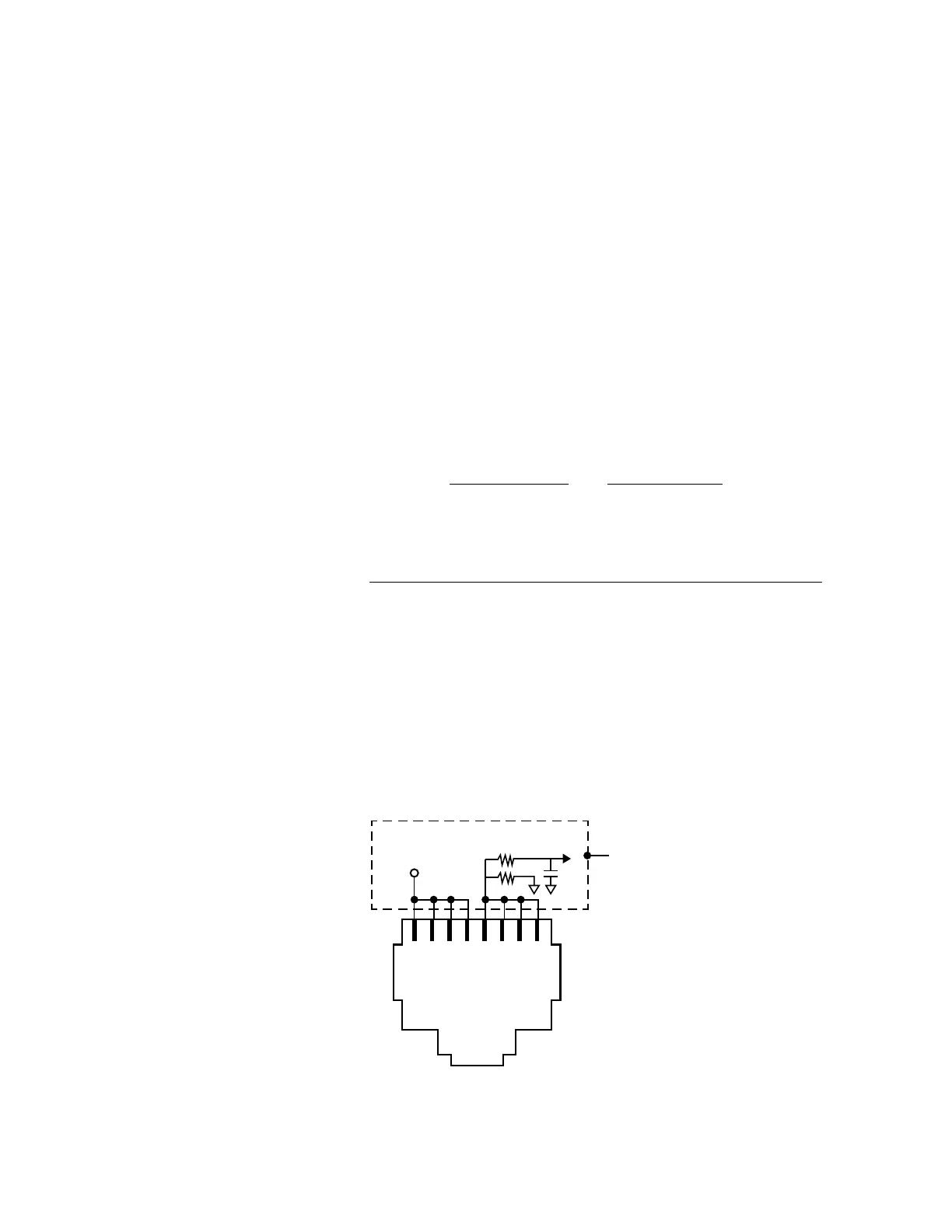
b) Wiring Connection: Output from the SSR Terminals on the Lithium Battery BMS should be wired to the RJ-
45 Jack marked “Battery Temp. Sensor” (6, Fig 2.1) as follows:
• Connect terminal marked “+” on the SSR (Drain of Mosfet switch inside SSR) to any of pins 1/2/3/4 of
RJ-45 Jack (Pinout shown below)
• Connect terminal marked “-” on the SSR (Source of Mosfet switch inside SSR) to any of pins 5/6/7/8 of
RJ-45 Jack (Pinout shown below)
1 2 3 4 5 6 7 8
+5V
Internal
Schematic
of EVO
TM
Batt Temp
to DSP
1K
5.1K
Pinout of RJ-45 Jack (marked "Battery Temp. Sensor") on the Front Panel of EVO (6, Fig 2.1)
SECTION 5 | Battery Charging in Evolution™ Series