EB8355-2EN 21
Mountingoncontrolvalves
Leftattachment Rightattachment
Mountingpositionontheplatelookingontothetravelpick-up(20),actuatorfacingupward(seealsoFig.7)
Actuatorwith“actuatorstemextends”(FA)fail-safeaction
Direct operating direction
>>
Reverse operating direction
<>
Direct operating direction
>>
Reverse operating direction
<>
Pneumatic connections Electrical connectionElectrical connection
Actuatorwith“actuatorstemretracts”(FE)fail-safeaction
Direct operating direction
>>
Reverse operating direction
<>
Direct operating direction
>>
Reverse operating direction
<>
Pneumatic connectionPneumatic connection Electrical connections
Fig.6: Attachment to the left or right of the valve for NAMUR attachment (IEC60534-6)
3.2 Attachmentaccordingto
IEC60534-6
Required mounting parts are listed in
Table5.Theratedtravelofthevalve
determines which lever and range spring
(Table6)arerequired.
An adapter housing is used for attachment
(Fig.7).Thevalvetravelistransmittedbythe
lever(18)andtheshaft(25)tothebracket
(28)oftheadapterhousingandthenpassed
ontothepin(27a)ontheleveroftheposi-
tioner.Toensurethatthepin(27a)isproper-
lylocatedinthebracket(28),xthespring
includedintheaccessoriesatthebackofthe
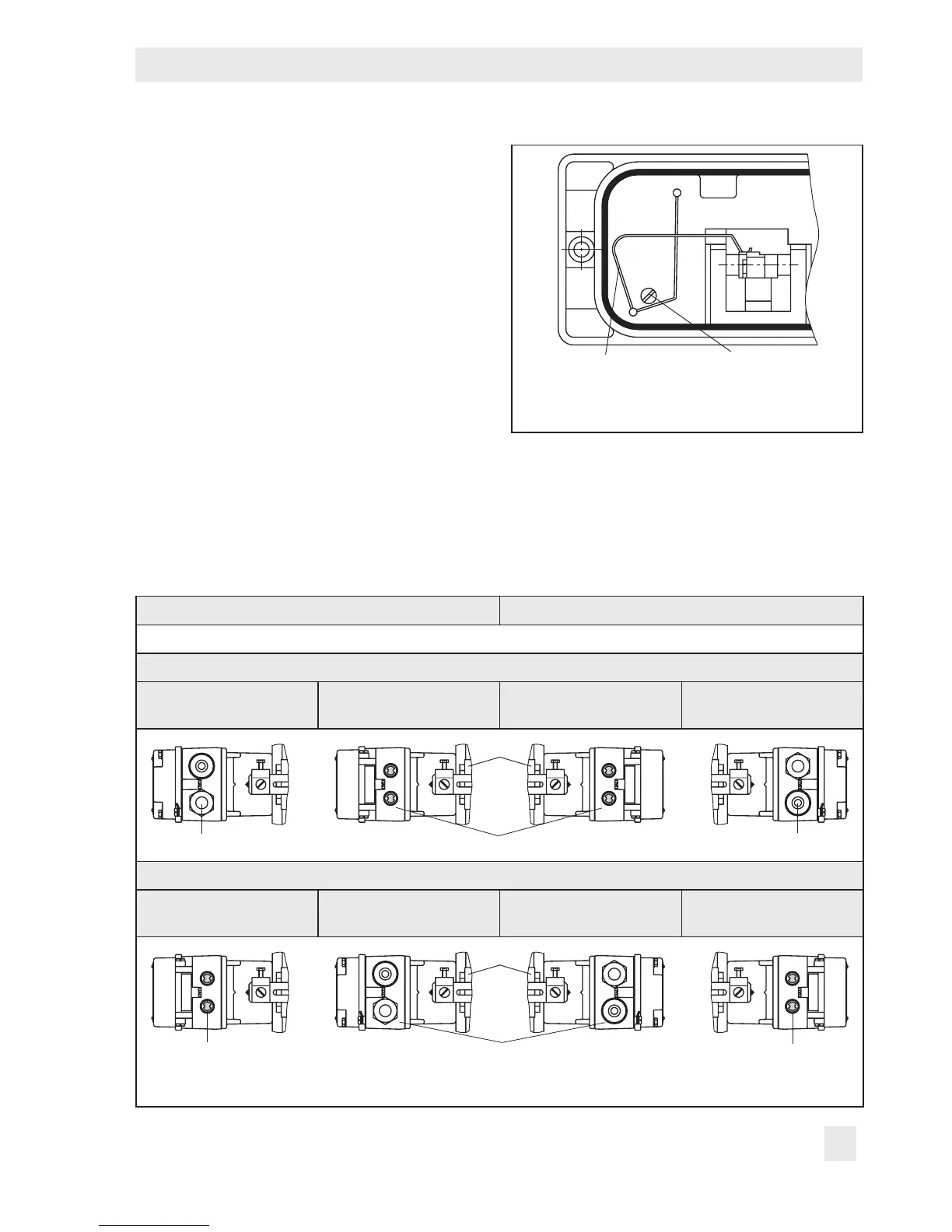
positionerhousingasillustratedinFig.5.
Spring Screw plug
Fig.5:Installing the spring on the back of the
housing
Thepositionercanbemountedeitheronthe
leftorrightsideofthecontrolvalve(Fig.6
andFig.7).Turnthepositionerattheadapt-
erhousingby180°todetermineorchange
the operating direction of the positioner/
control valve unit.