EB8355-2EN 37
Connections
Thewiresforthereferencevariablemustbe
connected to the terminals 11 and 12 locat-
ed in the housing.
In general, it is not necessary to connect the
positionertoabondingconductor.Should
thisberequired,however,thisconductorcan
beconnectedinsidethedeviceoroutsideon
the device.
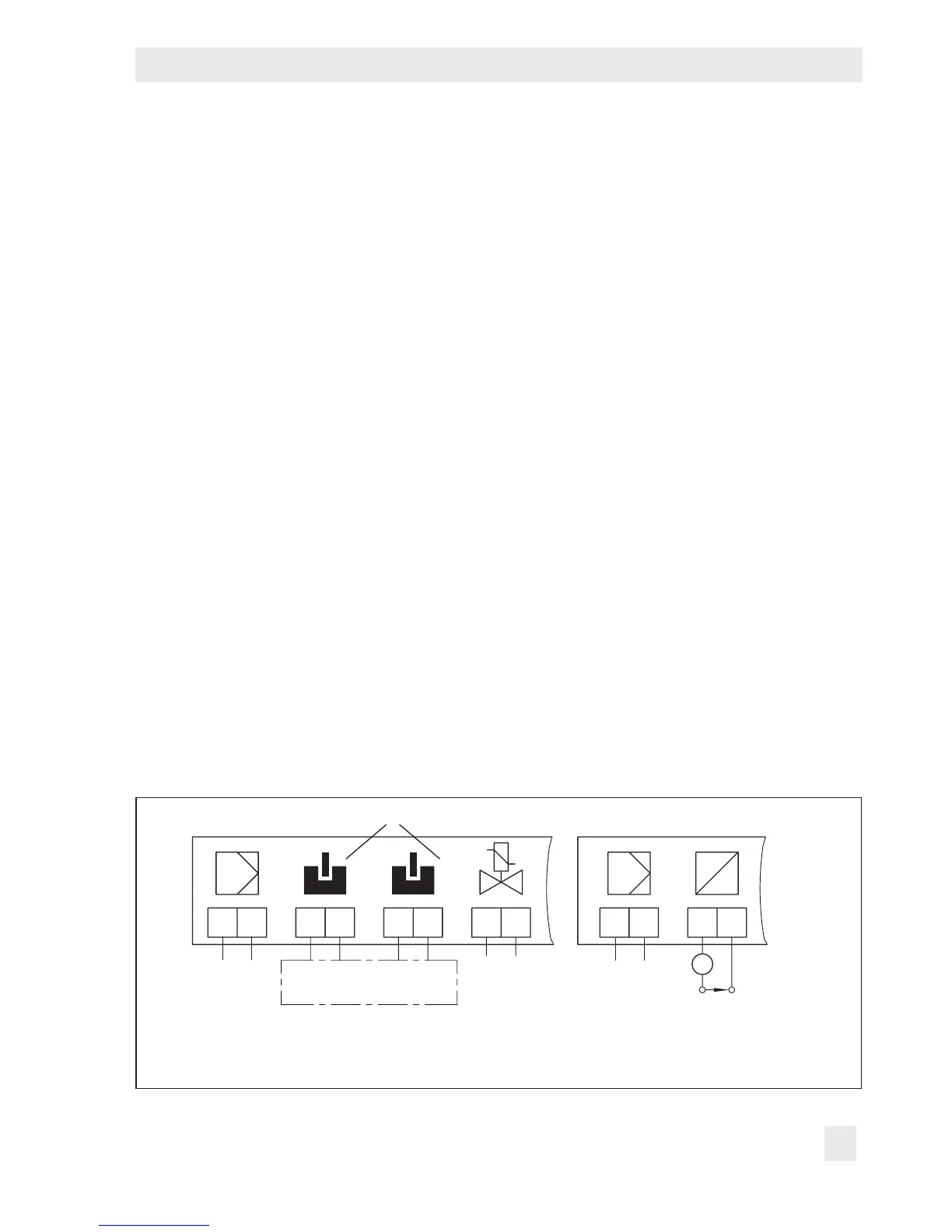
Depending on the version, the positioner is
equipped with inductive limit contacts and/
or a solenoid valve.
Versions with position transmitter do not per-
mit the connection of additional equipment.
The position transmitter is operated on a
two-wirecircuit.Theusualsupplyvoltageis
24VDC.
Taking the resistance of the supply leads into
account, the voltage at the position transmit-
terterminalscanbebetween12and
45VDC.
RefertoFig.12ortothelabelonthetermi-
nalblock.
Accessories:
Deviceindex3767-x...x.03 and lower
CableglandPG13.5
Black plastic Orderno.1400-6781
Blue plastic Orderno.1400-6782
Nickel-platedbrass Orderno.1400-6979
AdapterPG13.5to½NPT:
Metal to metal Orderno.1400-7109
Paintedblue Orderno.1400-7110
Deviceindex3767-x...x.04 and higher
CableglandM20x1.5
Black plastic Orderno.1400-6985
Blue plastic Orderno.1400-6986
Nickel-platedbrass Orderno.1890-4875
AdapterM20x1.5to½NPT:
Powder-coatedaluminum
Orderno.0310-2149
4.2.1 Switchingamplier
The operation of the inductive limit contacts
requiresswitchingampliersinaccordance
withEN60947-5-6tobeconnectedinthe
outputcircuit.Observetherelevantregula-
tions for installation in hazardous areas.
+41 –42 +51 –52 +81 –82 +31 –32
G
E
i