EB 8359-2 EN 5-7
Installation
For tight-closing valves, the maximum signal
pressure pst
max
is roughly estimated as fol-
lows:
pst
max
= F +
d² · π · ∆p
[bar]
4 · A
d = Seat diameter [cm]
∆p = Differential pressure across the valve
[bar]
A = Actuator area [cm²]
F = Upper bench range value [bar]
If there are no specications, calculate as
follows:
Required supply pressure =
Upper bench range value + 1bar
The positioner output pressure is routed to
the top or bottom diaphragm case of the ac-
tuator as shown in Fig.5-2 to Fig.5-5.
5.5 Selecting the range spring
The attached lever and the installed range
spring of the positioner are assigned to the
values of rated valve travel and the set point
as in Table 5-1.
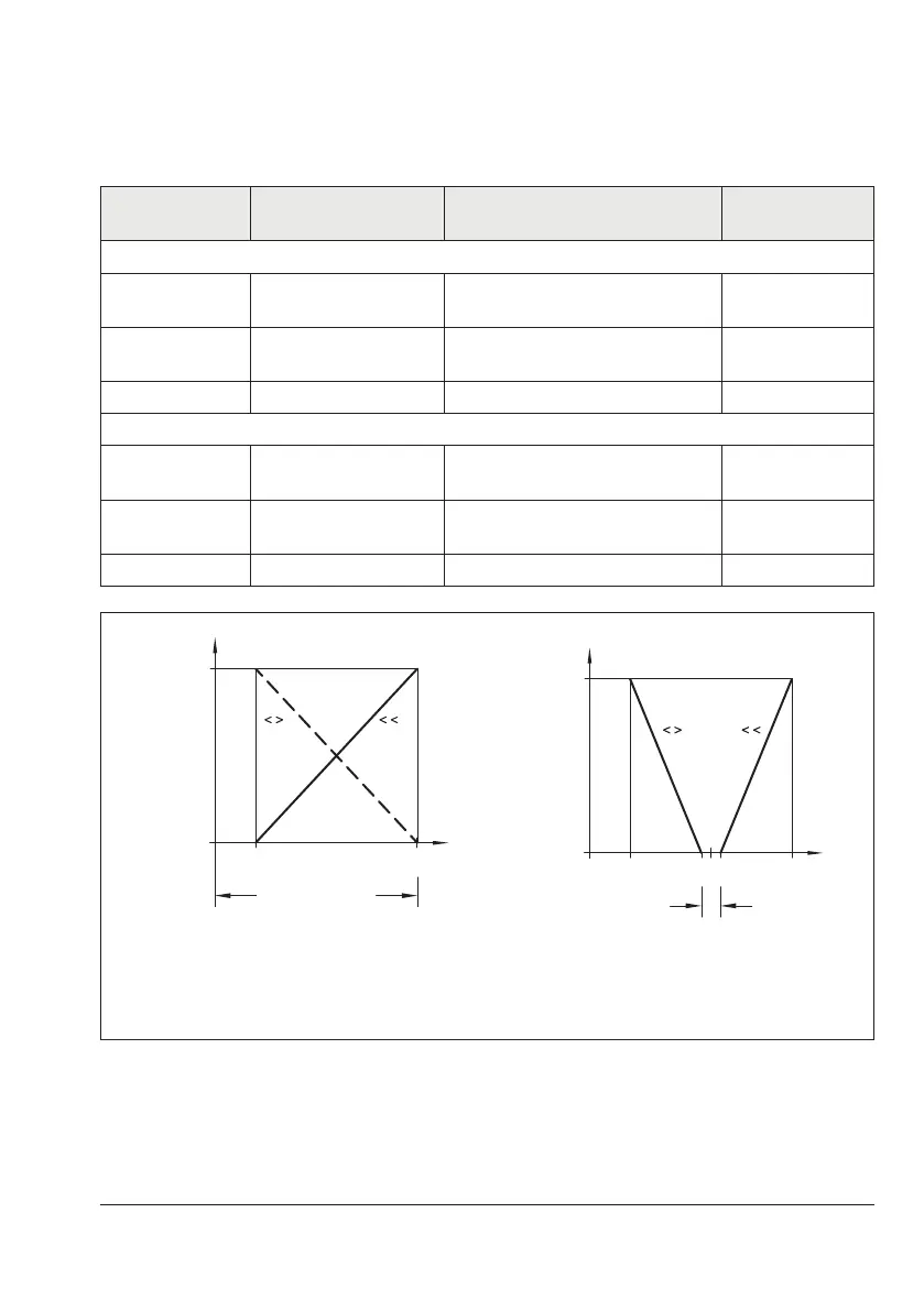
In normal operation, the set point span is
100% = 16mA. A smaller span of, for ex-
ample 50% = 8mA is only required for
split-range operation (Fig.5-8, right).
The span can be changed by exchanging the
range spring. On making adjustments to the
positioner, the travel must be adapted to the
set point and vice versa.
Table 5-1: Range springs
Rated travel
[mm]
Min./max. travel [mm] Set point (input signal) Range spring
Standard travels for SAMSON valves with lever l (40 to 127mm in length)
15 7.5 to 15
100%
50%
1
2
30 14 to 32
100%
50%
2
3
60 30 to 70 100% 3
Further travel ranges with lever l and lever extension (40 to 200mm in length)
20 7.5 to 26
100%
50%
1
2
40 14 to 50
100%
50%
2
3
> 60 30 to 90 100% 3
0%
4 20mA
Set point (input
signal)
Open
Travel
Closed
0%
412 20mA
Dead band
Valve 2 Valve 1
Open
Travel
Closed
Normal operation Split-range operation, two valves operating in
opposing directions
Fig.5-8: Normal or split-range operation