5-8 EB 8359-2 EN
Installation
With a set point, for example 4 to 20mA,
the valve must move through its entire travel
range from 0 to 100%. The starting point
then is 4mA and the upper range value
20mA.
In split-range operation, the controller output
signal is used to control two control valves,
dividing it such that the valves move through
their entire travel range at half the input sig-
nal range each (e.g. rst valve set to 4 to
12mA, second valve set to 12 to 20mA). To
avoid overlapping, allow for a dead band of
± 0.5mA as shown in Fig.5-8.
The starting point (zero) is adjusted at the
screw (4); the set point span, i.e. the upper
range value, is adjusted at the pin (2).
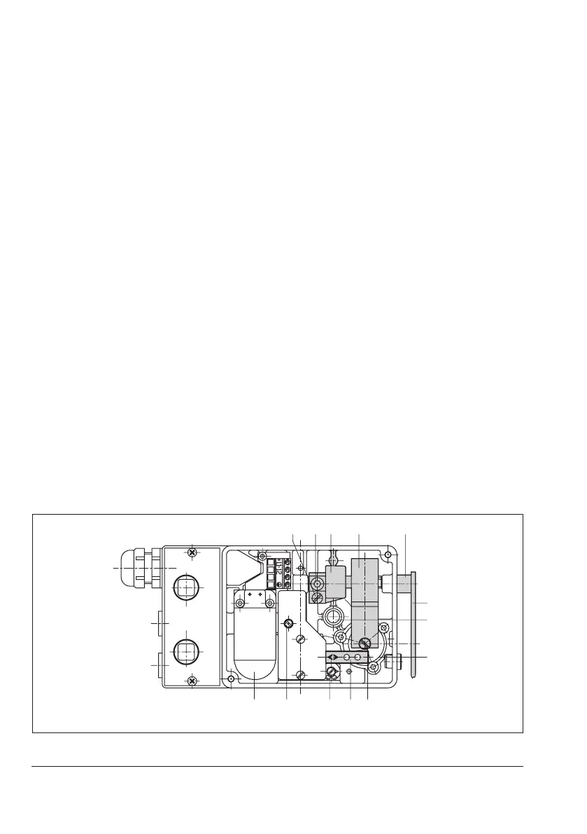
Exchanging the range spring (Fig.5-9)
Î Unscrew screw (7) on the range spring.
Undo hex socket screw (5) and pull out
the lever together with shaft.
Î Exchange range spring. Slide lever with
shaft through sleeve (3), positioner hous-
ing and bracket (6.1).
Î Secure range spring with the screw (7).
Î Move bracket and shaft until the screw
(5) sits on the attened part of the shaft.
Î Tighten screw (5). Allow for a play of
0.05 to 0.15mm between the lever (1)
and the sleeve (3) as well as between the
range spring (6) and the positioner hous-
ing.
1
15
8
Fig.5-9: Positioner with cover removed