9 Appendix
9.1 Menu structure
9.1.1 Heat exchangers WT1, WT2 and WT3
2
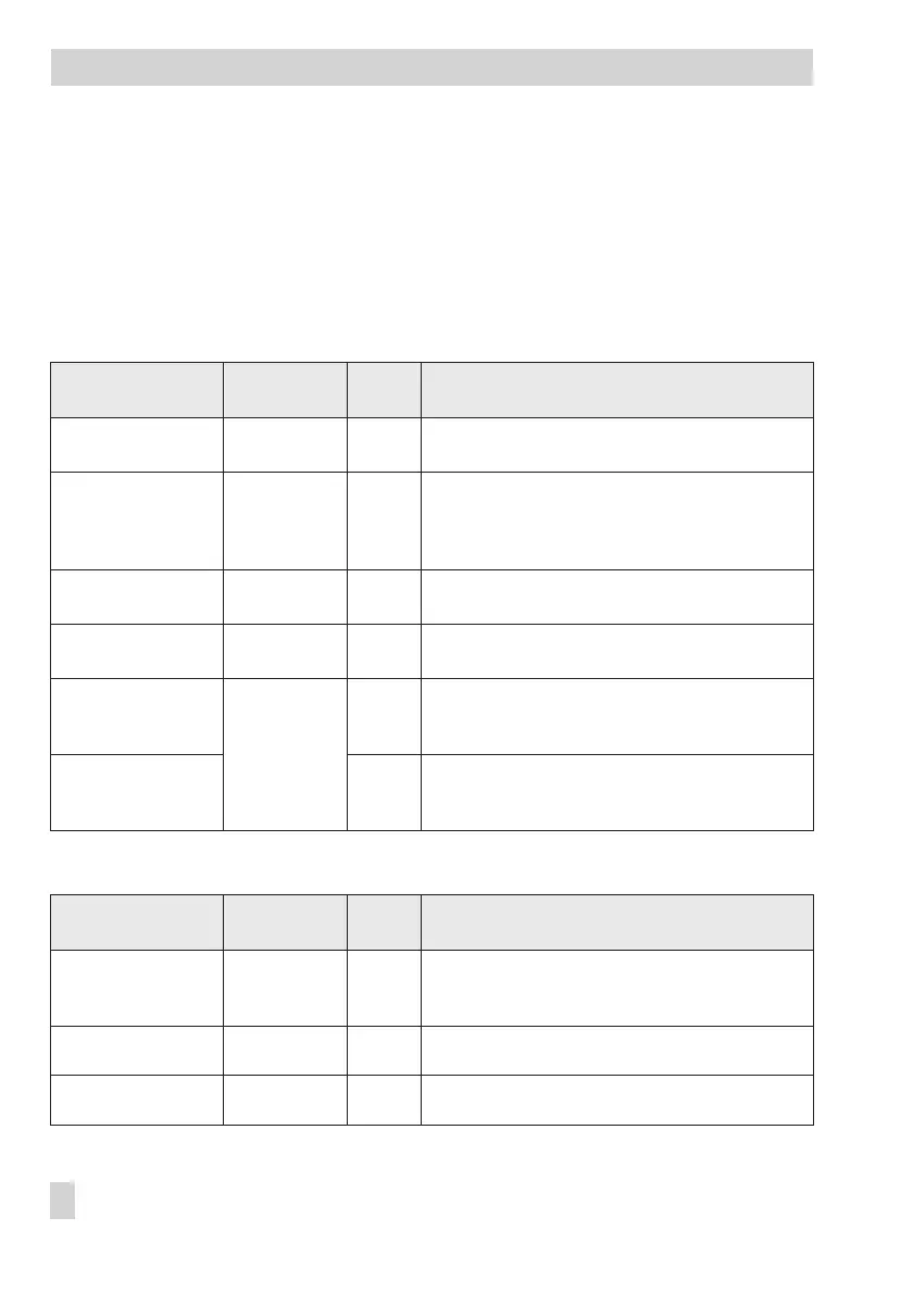
[Übersicht > Service > Wärmetauscher WT1 … WT3]
This menu can only be selected after the application key number has been entered!
Parameters Adjustment
range
WE Comments
Nennleistung (rating) 5 to 5000 kW 70 kW
Rating of heat exchanger; reference value for Unre
-
stricted sequence
Regelkreis (control cir
-
cuit)
3-Punkt
(three-step),
stetig (continu
-
ous)
3-Punkt Control algorithm of heat exchanger control circuit
Freigabe (enabling) EIN (on), BE
(binary input)
EIN Condition for sequence operation
SR-Eingang (position
feedback input)
1000–2000 Ohm,
0–10 V
1000–
2000 Ohm
Signal for position feedback
Ventil-Messbereich min
(min. valve measuring
range)
1000 to 2000 Ohm or
0 to 10V
1000 Ohm
Lower measuring range value
Ventil-Messbereich max
(max. valve measuring
range)
2000 Ohm
Upper measuring range value
2
[Übersicht > Parameter > Wärmetauscher WT1 … WT3]
Parameters Adjustment
range
WE Comments
Vorlauftemp. max
(max. flow tempera
-
ture)
20 to 120 °C 90 °C Upper limit for flow temperature
Einschaltzeit min
(min. activation time)
0 to 90 min 0 min
Time waited until heat exchanger deactivated
Ausschaltzeit min
(max. activation time)
0 to 90 min 0 min
Time waited until heat exchanger activated
74 EB 5571-2 EN
Appendix