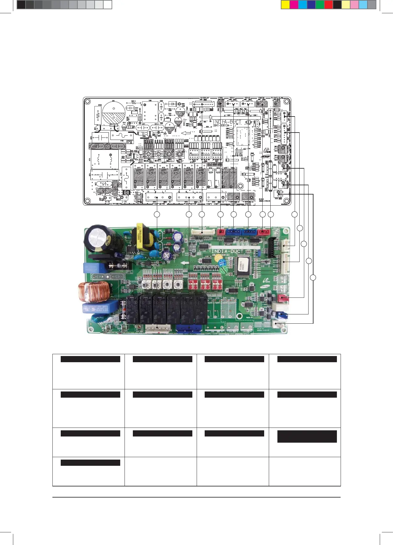
PCB Diagram and Parts List
6-17 Samsung Electronics
21 43 65 87
10
9
12
11
13
①
#1: N Phase
# 3: Fan Low Out
#5: Fan Mid Out
#7: Fan High Out
②
#1: N Phase
# 3: Fan Low Out
#5: Fan Mid Out
#7: Fan High Out
③④
⑤
#1~#4 : Rxd EEV control signal
#5 : 12V
⑥
#1~#4 : Rxd EEV control signal
#5 : 12V
⑦
#1,3: 12Vdc
#2: Error Check Out
#4: Comp. Check Out
⑧
⑨
#1,2 : Room
#3,4 : EVA1-IN
⑩
#1,2: EVA1-OUT
#3,4: EVA2-IN
#5,6: EVA2-OUT
⑪⑫
⑬
#1: 12Vdc
#2: Ground
CN62 - EEV1
CN61 - EEV2 CN81 - Operation Check Signal
CN10 - Download
CN73 - Fan Motor1 CN72 - Fan Motor2 CN91 - Display
CN83 - External Control Signal
CN41 - Temperature Sensor CN42 - Temperature Sensor CN31 - Communication1
CN33 - Wired Remote Controller
Communication
CN32 (2PIn/WHT): 12Vdc
6-17 Samsung Electronics
6-1-8 Duct type(SUPER)
■ MAIN PCB
$9;&6+B$BaLQGG