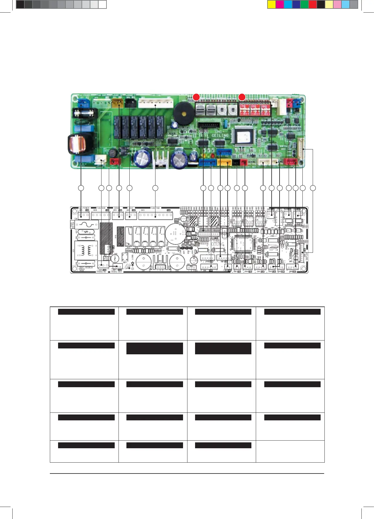
PCB Diagram and Parts List
6-23 Samsung Electronics
6-1-10 Celing type
①
#1: L Phase
#2: N Phase
②
③
④
#1: Input Operating Capacitor Motor
#2, #4: No Used
#3: Motor Control Signal
#5: N Phase Voltage
⑤
#1: DC12V
#2: GND
⑥
#1: Comm. Signal F1
#2: Comm. Signal F2
⑦
#1: Comm. Signal F3
#2: Comm. Signal F4
⑧
#1~5: LED Control
#6: Auto_S/W
#7:Remocon_Signal
#8:GND
#9: VCC
⑨
#1,3: DC12V
#2: Error CHK Out
#4: Comp. CHK Out
⑩
#1: EVA OUT THEMISTOR
#2: GND
⑪
#1: ROOM Temp. Sensor
#2: GND
#3: EVA IN Temp. sensor
#4: GND
⑫
#1: On/off Contact point input
#2: GND
⑬
#1: GND
#2: Float S/W
⑭⑮
#1: DC12V
#2~5: LOUVER control
⑯
#1: DC12V
#2: -
#3: GND
⑰
#1: N
#2: L
⑱⑲
#1: EEV
#2: DC12V
CN32- Remocon DC12V
CN31- Indoor/Outdoor Unit
Communication
CN33- Wired Remocon
Communication
CN91-Display
CN71-AC Power CN74-Drain Pump
CN75 Ventilator
CN73-Fan Motor
CN81- External Control OUT CN42- Temp. Sensor
CN41- Temp. sensor
CN83- External Control
CN51-Float S/W
CN76-SUB PCB Connetction
CN61-LOUVER
CN11-TRANS-OUT
CN62- EEV
CN72-Trans In CN10-Micom Download
1 2 3 4 18 19 5 6 817 16 15 13 12 11 10 79
A
B
14
$9;&6+B$BaLQGG