13
INSTALLATION
y
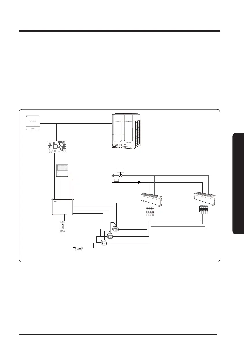
Water sensor should be attached to inlet pipe (1) for 2 pipe system (Water In), and each
inlet pipe (2) for 4 pipe system (Cooling pipe In/Heating pipe In).
y
Maximum number of FCU KITs that can be installed and controlled simultaneously by a
wired remote controller is 16.
Integrated control of FCU
y
Install FCUs and FCU KIT by multiple FCUs to 1 FCU KIT.
CN4
CN3
RED
CN2
BLK
YEL
RED
Y-GRN
DMS
M
Water IN sensor
LOW
MID
HIGH
LOW
MID
HIGH
AC Water Valve 0.5 A
AC 208 ~ 230 V 60 Hz,
AC 220 ~ 240 V 50 Hz
AC 208 ~ 230 V 60 Hz,
AC 220 ~ 240 V 50 Hz
FCU interface module
Wired remote
controller
DVM CHILLER
Relay
L
N
Terminal block
COMMON
FCU KIT
y
National electric appliance safety standard should be applied for relay installation and
capacity and power cable connection of FCU terminal block.