Optical Tunable Filter OTF-930
4-1
4
Principle of Operation
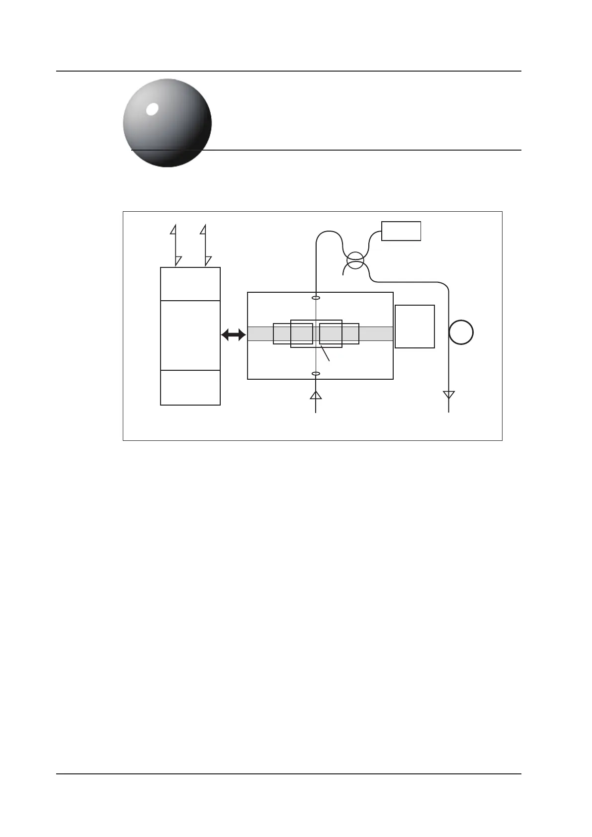
The gure above shows a schematic diagram of the OTF-930. Two lter elements, each with a
40nm wavelength range, are mounted on a stepper motor driven slider. Light is collimated by a lens
and passes directly through the lter. The slider is automatically controlled to provide seemless
wavelength tuning over the full 80nm range. The ltered light is coupled back into a ber and a
small portion is tapped onto a photodetector. This enables accurate power monitoring of the ltered
CPU
Communication
Interface
Display
Motor
IN
PD
OUT
GPIB
RS-232C
L
1
FL1
L
1,
L
2 :
Lens
FL
1,FL2:Filter
L
2
FL2
Slider