-31-
Electrical Adjustments
PC, Video, Component Manual adjustment
[1] Manual adjustment (PC)
Input mode Computer 1 (RGB) mode
Input signal 16-step gray scale computer signal
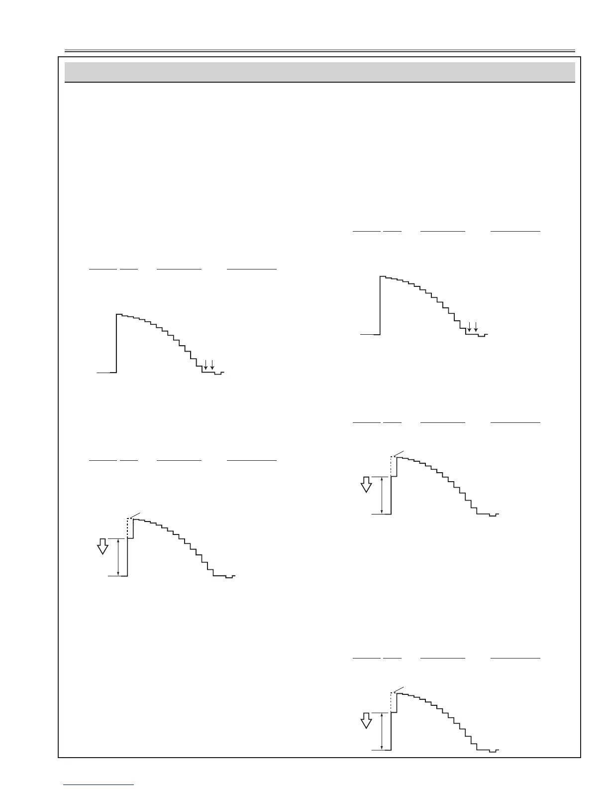
- Pedestal adjustment
1. Enter the service mode.
2. Adjust the pedestal level and black level to be the
same level by changing the data values of the Group
- No.
Group No. Test Point Adjustment
0 - 0 TP35G ADC G-Offset
0 - 1 TP35R ADC R-Offset
0 - 2 TP35B ADC B-Offset
Pedestal Lebel
Black Lebel
- Gain adjustment
1. Enter the service mode.
2. Adjust the amplitude “a” to be minimum by changing
the data values of the Group - No.
Group No. Test Point Adjustment
0 - 3 TP35G ADC G-Gain
0 - 4 TP35R ADC R-Gain
0 - 5 TP35B ADC B-Gain
[2] Manual adjustment (Component)
Input mode Computer 1 (Component) mode
Input signal 16-step gray scale component signal
(480i)
- Pedestal adjustment
1. Enter the service mode.
2. Adjust the pedestal level and black level to be the
same level by changing the data values of the Group
- No.
Group No. Test Point Adjustment
0 - 0 TP35G ADC G-Offset
0 - 1 TP35R ADC R-Offset
0 - 2 TP35B ADC B-Offset
Pedestal Lebel
Black Lebel
- Gain adjustment
1. Enter the service mode.
2. Adjust the amplitude “a” to be minimum by changing
the data values of the Group - No.
Group No. Test Point Adjustment
0 - 3 TP35G ADC Y-Gain
When the PC, Video or Component Auto Calibration
fails, take the following manual adjustment instead of
auto calibration.
[3] Manual adjustment (Video)
Input mode Video (Video) mode
Input signal 16-step gray scale composite video
signal
- Gain adjustment
1. Enter the service mode.
2. Adjust the amplitude “a” to be minimum by changing
the data values of the Group - No.
Group No. Test Point Adjustment
20 - 0 TP35G Y-Level
 Loading...