EasyManuals Logo

Sanyo PLC-XF1000 Service Manual

Sanyo PLC-XF1000
234 pages
To Next Page IconTo Next Page
To Previous Page IconTo Previous Page
Page #54 background imageLoading...
Page #54 background image
-54-
Optical Adjustment
Blue band Yellow bandBlue band
Yellow band
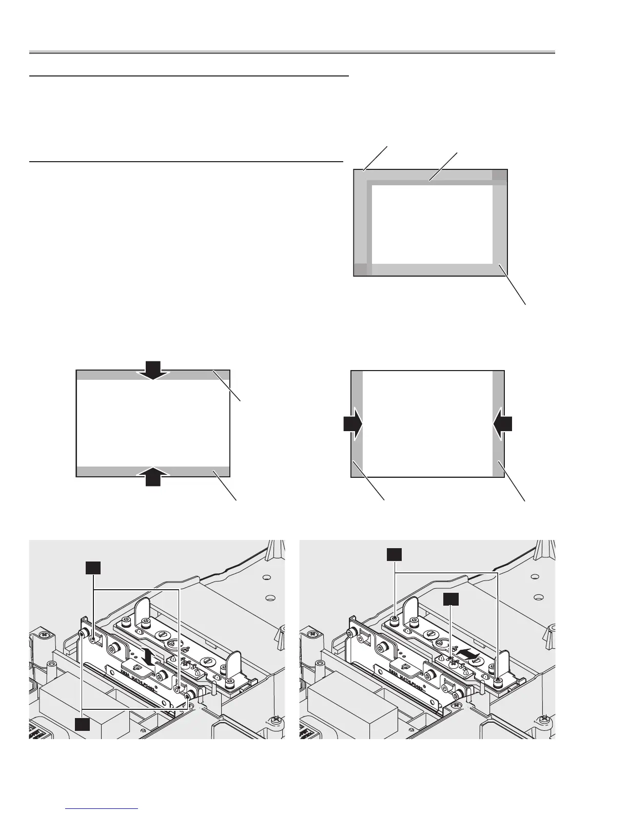
z Integrator adjustment-1
1 Move the Integrator-out and Integrator-in to display the color bands
on the top/bottom or left/right of the screen.
1) To adjust the image vertically as shown in Fig.1-1, loosen 2
screws A, and turn the screws B by using hex drivers.
2) To adjust the image horizontally as shown in Fig.1-2, loosen 2
screws C, and move the slot D by using a slot screwdriver.
2 Tighten screws A and C to fix the Integrator-out and Integrator-in
unit.
Color edge
Blue band
Yellow band
Fig.1-1
Fig.1-2
(Target screen image)
A
B
C
D
1. Optical Center adjustment
Take step-z to step-v for the optical center adjustment.
Disconnect the FPC cables of the panels and replace each polarized
glass/optical filter ass'y with the adjustment tool. Set the main board
into the groove on the optical unit top. (See the previous pages)

Table of Contents

Other manuals for Sanyo PLC-XF1000

Questions and Answers:

Question and Answer IconNeed help?

Do you have a question about the Sanyo PLC-XF1000 and is the answer not in the manual?

Sanyo PLC-XF1000 Specifications

General IconGeneral
Vertical scan range48 - 120 Hz
Horizontal scan range15 - 120 kHz
Projection technologyLCD
Contrast ratio (typical)4000:1
Projector native resolutionXGA (1024x768)
Resolution2359296 pixels
Aspect ratio4:3
RS-232 ports1
Dimensions (WxDxH)530 x 269 x 756 mm
Lamp power330 W
Light source typeLamp
Service life of light source (economic mode)3000 h
Serial interface typeRS-232
Power consumption (economy mode)770 W
Weight and Dimensions IconWeight and Dimensions
Weight27578 g

Related product manuals