-33-
Electrical Adjustments
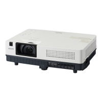
Gain adjustment [PC]
1. Enter the service mode.
2. Receive the 16-step grey scale computer signal with
Computer1 [RGB] mode.
3. Connect an oscilloscope to test point “TP35G” (+)
and chassis ground (-).
4. Select Group No. “0”, Item No. “3” and adjust the
amplitude “a” to be minimum by changing the Data
value.
5. Connect an oscilloscope to test point “TP35R” (+)
and chassis ground (-).
6. Select Group No. “0”, Item No. “4” and adjust the
amplitude “a” to be minimum by changing the Data
value.
7. Connect an oscilloscope to test point “TP35B” (+) and
chassis ground (-).
8. Select Group No. “0”, Item No. “5” and adjust the
amplitude “a” to be minimum by changing the Data
value.
Pedestal adjustment [Component]
1. Enter the service mode.
2. Receive the 16-step grey scale 480i-component signal
with Computer1 [Component] mode.
3. Connect an oscilloscope to test point “TP35G” (+)
and chassis ground (-).
4. Select Group No. “0”, Item No. “0” and change data
value to adjust the pedestal level and black level to be
the same level.
5. Connect an oscilloscope to test point “TP35R” (+)
and chassis ground (-).
6. Select Item No. “1” and change data value to adjust
the pedestal level and black level to be the same lev-
el.
1. Enter the service mode.
2. Receive the 8 color 100% color bar 480i-component
signal with Computer1 [Component] mode.
3. To start the auto-calibration for Component adjust-
ment, select Group No. “260”, Item No. “0” and then
change data value from “0” to “1”. After the auto-cali-
bration completed, "OK" will appear on the screen.
4. Auto Calibration adjustment [Component]
Below adjustments are performed when the above
auto calibration is failed.
7. Connect an oscilloscope to test point “TP35B” (+)
and chassis ground (-).
8. Select Item No. “2” and change data value to adjust
the pedestal level and black level to be the same lev-
el.
Pedestal Lebel
Black Lebel
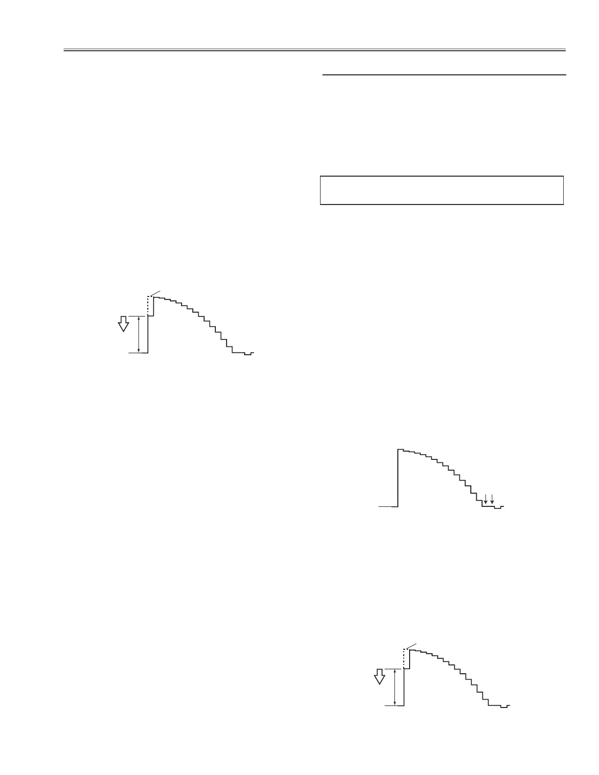
Gain adjustment [Component]
1. Enter the service mode.
2. Receive the 16-step grey scale 480i-component signal
with Computer1 [Component] mode.
3. Connect an oscilloscope to test point “TP35G” (+)
and chassis ground (-).
4. Select Group No. “0”, Item No. “3” and adjust the
amplitude “a” to be minimum by changing the Data
value.
 Loading...