-7-
Electrical Adjustments
1. Receive the 16-step gray scale computer signal with
Input 1 [COMPUTER] mode.
2. Enter the service mode.
3. Select group no. “4”, item no. “6” and change data
value to reproduce the proper gray scale picture on
the screen.
PC Gamma Shift adjustment
[480p-PEDESTAL ADJUSTMENT]
1. Receive the 16-step gray scale component signal
[480p] with Input 3 [COMPONENT] mode.
2. Enter the service mode.
3. Connect an oscilloscope to test point “TP21G”(+)
and chassis ground (-).
4. Select group no. “3”, item no. “1” and change data
value to adjust the pedestal level and black level to be
the same level.
5. Connect an oscilloscope to test point “TP21B”(+)
and chassis ground (-).
6. Select group no. “5”, item no. “14” and change data
value to adjust the pedestal level and black level to be
the same level.
7. Connect an oscilloscope to test point “TP21R”(+)
and chassis ground (-).
8. Select item no. “13 and change data value to adjust
the pedestal level and black level to be the same
level.
[1080i-PEDESTAL ADJUSTMENT]
1. Receive the 16-step gray scale component signal
[1080i] with Input 3 [COMPONENT] mode.
2. Enter the service mode.
3. Connect an oscilloscope to test point “TP21G”(+)
and chassis ground (-).
4. Select group no. “3”, item no. “1” and change data
value to adjust the pedestal level and black level to be
the same level.
5. Connect an oscilloscope to test point “TP21B”(+)
and chassis ground (-).
6. Select group no. “5”, item no. “14” and change data
value to adjust the pedestal level and black level to be
the same level.
7. Connect an oscilloscope to test point “TP21R”(+)
and chassis ground (-).
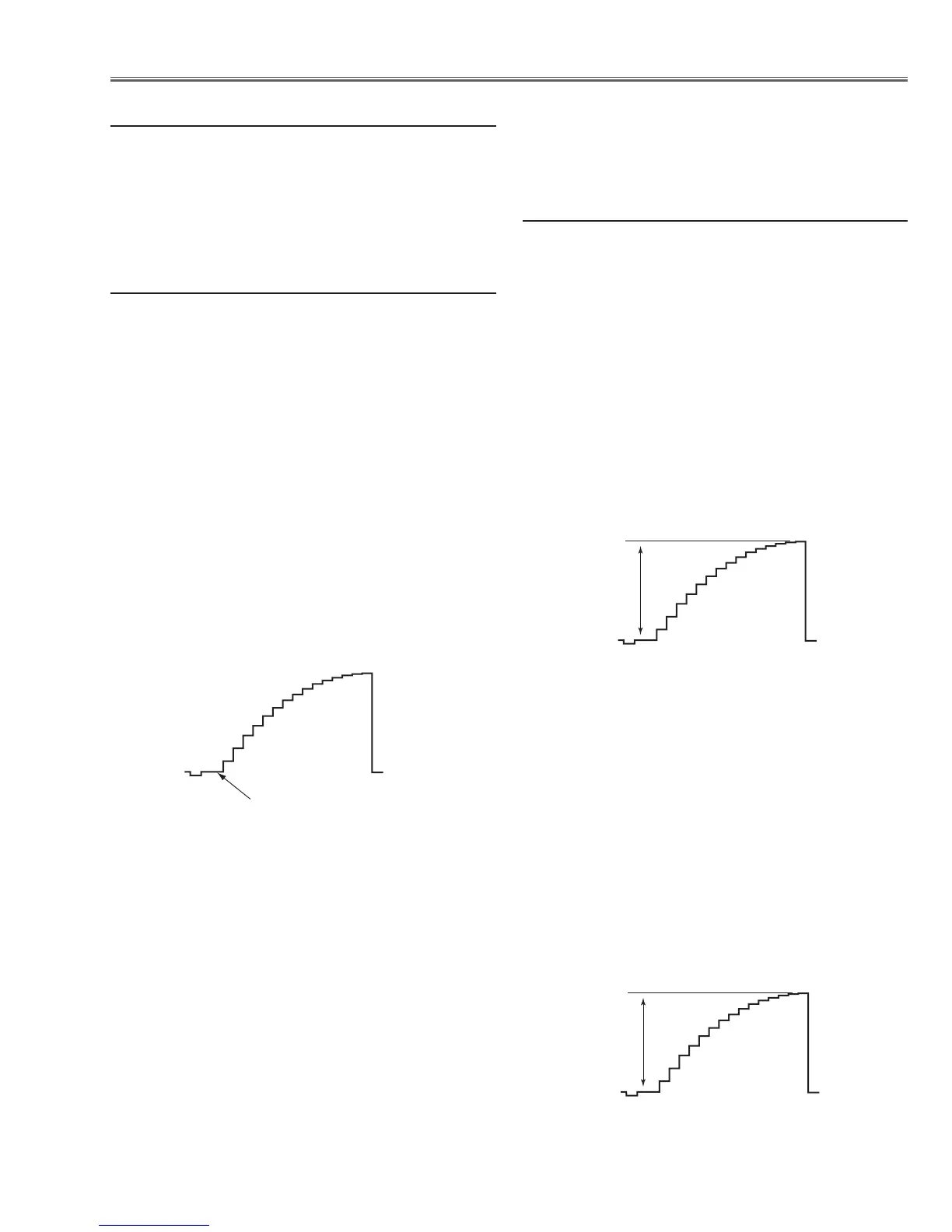
Pedestal Lebel = Black Lebel
HDTV Pedestal adjustment
8. Select item no. “13 and change data value to adjust
the pedestal level and black level to be the same
level.
[480p-A/D INPUT ADJUSTMENT]
1. Receive the 16-step gray scale component signal
[480p] with Input 3 [COMPONENT] mode.
2. Enter the service mode.
3. Connect an oscilloscope to test point “TP21G”(+)
and chassis ground (-).
4. Select group no. “3”, item no. “0” and change data
value to adjust amplitude “a” to be 0.9 ±0.1V.
5. Connect an oscilloscope to test point “TP21B”(+)
and chassis ground (-).
6. Select item no. “4” and change data value to adjust
amplitude “a” to be 0.9 ±0.1V.
7. Connect an oscilloscope to test point “TP21R”(+)
and chassis ground (-).
8. Select item no. “2 and change data value to adjust
amplitude “a” to be 0.9 ±0.1V.
[1080i-A/D INPUT ADJUSTMENT]
1. Receive the 16-step gray scale component signal
[1080i] with Input 3 [COMPONENT] mode.
2. Enter the service mode.
3. Connect an oscilloscope to test point “TP21G”(+)
and chassis ground (-).
4. Select group no. “
3”, item no. “0” and change data
value to adjust amplitude “a” to be 0.9 ±0.1V.
5. Connect an oscilloscope to test point “TP21B”(+)
and chassis ground (-).
6. Select item no. “4” and change data value to adjust
amplitude “a” to be 0.9 ±0.1V.
7. Connect an oscilloscope to test point “TP21R”(+)
and chassis ground (-).
8. Select item no. “2 and change data value to adjust
amplitude “a” to be 0.9 ±0.1V.
Note: This adjustment should be done after HDTV
Pedestal adjustment.
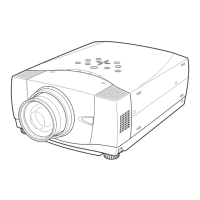
(a)
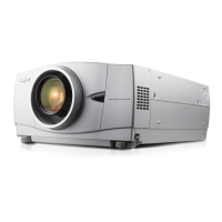
(a)
HDTV A/D Input adjustment