EasyManuals Logo

Sanyo PLC-XU101 Service Manual

Sanyo PLC-XU101
108 pages
To Next Page IconTo Next Page
To Previous Page IconTo Previous Page
Page #13 background imageLoading...
Page #13 background image
-13-
Mechanical Disassembly
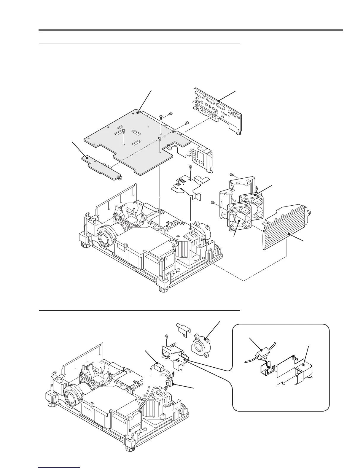
x Main, AV Board, Rear Panel and Fans Board removal
Main board
Rear panel
(M2.5x6)
Fig.2
AV board
(M2.5x6)x5
Side grill
(T3x6)x2
(T3x6)(Black)x2
1. Remove the Main board.
2. Remove the Rear panel.
3. Remove AV board.
4. Remove fans (FN901, FN902).
FN901
FN902
(T3x8)
(M3x8)
FN907
1. Disconnect the lamp ballast socket and
remove fan (FN907)
Fig.3
c Fan (FN907) removal
Trigger
Trigger
Duct
* Trigger should be mounted as
the figure above.
Ballast
socket

Table of Contents

Other manuals for Sanyo PLC-XU101

Questions and Answers:

Question and Answer IconNeed help?

Do you have a question about the Sanyo PLC-XU101 and is the answer not in the manual?

Sanyo PLC-XU101 Specifications

General IconGeneral
Matrix size0.8 \
Vertical scan range50 - 100 Hz
Horizontal scan range15 - 100 kHz
Projection technologyLCD
Contrast ratio (typical)500:1
Screen size compatibility33 - 300 \
Projector native resolutionXGA (1024x768)
Keystone correction, vertical±40 °
OutputD-Sub15 x 1
Video inRCA x 1
Audio inputYes
Aspect ratio4:3
Dimensions (WxDxH)334 x 232 x 78 mm
Connectivity technologyWired
Lamp power275 W
Light source typeLamp
Noise level29 dB
Dot clock scanning frequency140 MHz
Audio (L/R) in2
Headphone outputs1
Display resolution786 x 432 pixels
Power consumption (typical)385 W
Weight and Dimensions IconWeight and Dimensions
Weight3500 g

Related product manuals