-23-
Electrical Adjustments
1. Receive the 16-step grey scale computer signal with
Computer2 [RGB] mode.
2. Enter the service mode.
3. Connect an oscilloscope to test point “TPG1” (+) and
chassis ground (-).
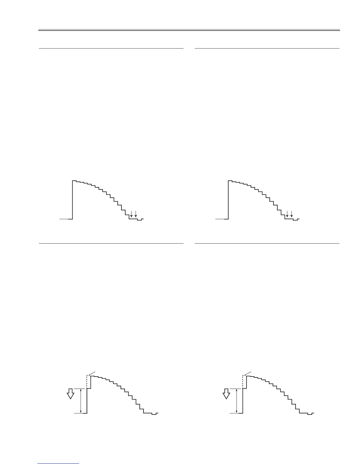
4. Select group no. “
0”, item no. “0” and change data
value to adjust the pedestal level and black level to
be the same level.
5. Connect an oscilloscope to test point “
TPR1” (+) and
chassis ground (-).
6. Select item no. “
1” and change data value to adjust
the pedestal level and black level to be the same
level.
7. Connect an oscilloscope to test point “
TPB1” (+) and
chassis ground (-).
8. Select item no. “
2” and change data value to adjust
the pedestal level and black level to be the same
level.
Pedestal Lebel
Black Lebel
x Pedestal adjustment [PC]
1. Receive the 16-step grey scale component signal
with Computer2 [Component1080i] mode.
2. Enter the service mode.
3. Connect an oscilloscope to test point “
TPG1” (+) and
chassis ground (-).
4. Select group no. “
0”, item no. “0” and change data
value to adjust the pedestal level and black level to
be the same level.
5. Connect an oscilloscope to test point “
TPR1” (+) and
chassis ground (-).
6. Select group no. “
0”, item no. “1” and change data
value to adjust the pedestal level and black level to
be the same level.
7. Connect an oscilloscope to test point “
TPB1” (+) and
chassis ground (-).
8. Select group no. “
0”, item no. “2” and change data
value to adjust the pedestal level and black level to
be the same level.
Pedestal Lebel
Black Lebel
v Pedestal adjustment [1080i]
1. Receive the 16-step grey scale computer signal with
Computer2 [RGB] mode.
2. Enter the service mode.
3. Connect an oscilloscope to test point “TPG1” (+) and
chassis ground (-).
4. Select group no. “
0”, item no. “3” and adjust the
amplitude “a” to be minimum by changing the Data
value.
5. Connect an oscilloscope to test point “
TPR1” (+) and
chassis ground (-).
6. Select item no. “
4” and adjust the amplitude “a” to be
minimum by changing the Data value.
7. Connect an oscilloscope to test point “TPB1” (+) and
chassis ground (-).
8. Select item no. “
5” and adjust the amplitude “a” to be
minimum by changing the Data value.
c Gain adjustment [PC]
1. Receive the 16-step grey scale component signal
with Computer2 [Component1080i] mode.
2. Enter the service mode.
3. Connect an oscilloscope to test point “TPG1” (+) and
chassis ground (-).
4. Select group no. “
9”, item no. “0” and adjust the
amplitude “a” to be minimum by changing the Data
value.
5. Connect an oscilloscope to test point “
TPR1” (+) and
chassis ground (-).
6. Select item no. “
1” and adjust the amplitude “a” to be
minimum by changing the Data value.
7. Connect an oscilloscope to test point “TPB1” (+) and
chassis ground (-).
8. Select item no. “
2” and adjust the amplitude “a” to be
minimum by changing the Data value.
b Gain adjustment [1080i]

 Loading...