-16-
5
8
Fig.8
1
6
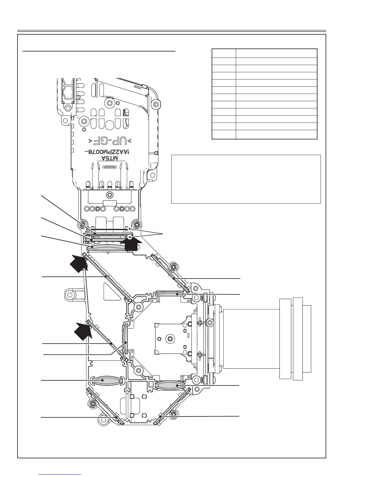
No. Parts Name
1 Integrator lens (OUT)
2 Prism beam splitter (PBS)
3 Condenser lens (OUT)
4 Dichroic mirror (B)
5 Dichroic mirror (G)
6 Condenser lens (G)
7 Mirror (R)
8 Condenser lens (R)
9 Condenser lens (B)
10 Mirror (B)
9
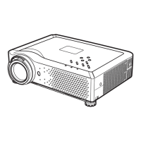
Optical Parts Disassembly
When mounting or assembling the optical parts in the
optical unit, the parts must be mounted in the specified
location and direction as shown in figure below.
The arrows in the figure indicate the mount direction
of the part for the replacement. Check the number on
the arrows and mount each part according to its note;
A: The printed part no. comes to this side.
B: Rugged surface comes to this side.
2
3
4
7
7
10
, Locations and Directions
A
A
B
slit
8

 Loading...