7. EXPLANATION OF PARAMETERS
7-5
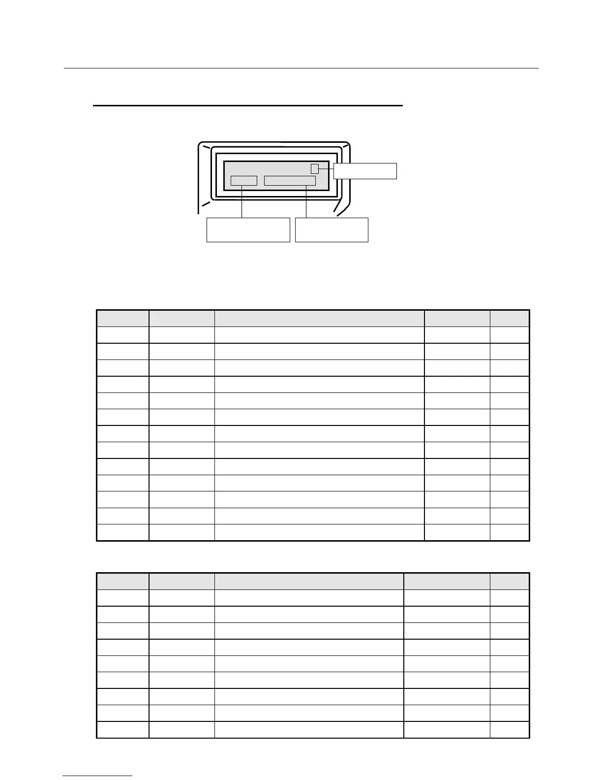
7.1.4 Parameter Setting Mode (Screen Mode 0 to 2 and 8)
Various Servo Amplifier parameters can be directly set in this mode from the keys.
Fig. 7-3 Parameter Setting Mode Screen
Table 7-4 Parameters for Screen Mode 0
Page No. Abbreviation Name Setting range Unit
0 KpM Monitors position loop gain - rad/S
1 KffM Monitors feed forward gain - %
2 KvpM Monitors velocity loop proportional gain - Hz
3 TviM Monitors velocity loop integral time constant - mSec
4 FLPM Monitors feed forward LPF - Hz
5 VLPM Monitors velocity command LPF - Hz
6 ILPM Monitors current command LPF - Hz
7 BFAM Monitors current command BEFA - Hz
8 BFBM Monitors current command BEFB - Hz
9 Tpcm Position command LPF time constant 0 to 4000 mSec
10 Tvac Velocity command acceleration time 0 to 9999 mSec
11 Tvde Velocity command deceleration time 0 to 9999 mSec
12 KvpA Velocity loop proportional gain addition value 0 to 255 Hz
Table 7-5 Parameters for Screen Mode 1 (1/2)
Page No. Abbreviation Name Setting range Unit
0 INP Positioning complete signal width 1 to 32767 P (+/−)
1 OVF Excess deviation over value 1 to 32767 ×256P
2 EGER Electronic gear ratio 1/32767 to 32767/1
3 PMUL Command pulse multiplier 1 to 63
4 ENCR Output pulse dividing ratio 1 to 8192
5 LTG Low speed 0 to 32767 min
-1
6 HTG High speed 0 to 32767 min
-1
7 SPE Speed matching width 0 to 32767 min
-1
8 VCI1 Internal velocity command value 1 0 to 32767 min
-1
*Para. Set #
#### #########
Screen page