4. WIRING
4-5
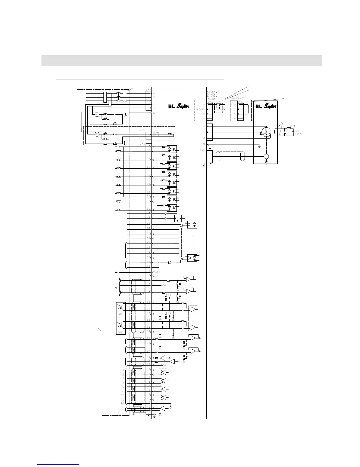
4.3 External Wiring Diagram
4.3.1 External Wiring Diagram (200 VAC Input Type)
Fig. 4-1 (a) External Wiring Diagram (200 VAC Input Type)
AC power supply 3φ
200 to 230 V
50/60 Hz
User unit
En-
coder
SERVO
Orange (yellow)
Holding brake
(for the type with
a brake only)
Short bar
Note 15)
SERVO AMPLIFIER
Note 3)
Note 16)
Note 14)
Note 17
Start ready ON
System error
System error
DC 5 V to 24
Servo ON
Alarm reset
Current limit permit
Note 9) Forward revolution
overtravel
Note 9) Backward revolution
overtravel
Note 10) General-purpose
input
Note 10) General-purpose
input
Note 10) General-purpose
input
Note14) 12 VDC to 24 V
Note 11) General-purpose output
Note 11) General-purpose output
Start ready complete output
Holding brake relay excitation
timing output
LM1
ALM2
Note 12) Alarm output
ALM4
ALM8
Output common
Note 13) Forward revolution
current limit
Note 18) Lithium battery
3.6 VDC
Note 13) Backward revolution
current limit
Note 8) Line driver 26LS31
Note 8) Velocity command input
Note 8) Torque compensation/
command input
Monitor 1
Monitor 2
Monitor common
Note 18) Encoder signal
Open collector output
Plug: 10150−3000 VE, Shell: 10350-52A0-008
Forward
revolution
pulse
Backward
revolution
pulse
Position
command
pulse input
Start ready OFF
Start ready OFF
Note 19)
Note 14) 5 VDC
Built-in type
regenerative resistor
When connecting an external
regenerative resistor
Note 4) PY2A050 built-in type
regenerative resistor
Regenerative resistor
Note 4)
Note 6) Red
White
Black
(Green/yellow)
Green
Note 7)
Plug : 10120-3000VE,
Shell : 10320-52A0-008
Note 5)
Sensor connector
Series regulator
Note 2)
Line receiver:
26LS32
Line driver: 26LS31
Note 5)