4. WIRING
4-2
4.1 Applicable Wire Sizes
• The table below shows typical sizes of external terminals and wires used for the Servo Amplifier.
• Select the wire to use and its size based on the wiring distance, operation environment and current
capacity.
• Table 4-1 assumes that the rated current flows on three lead wiring harnesses at an ambient
temperature of 104°F (40°C).
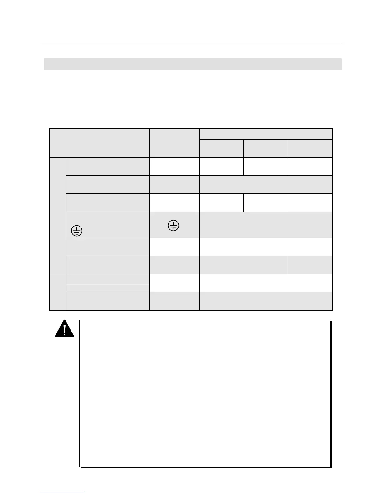
Table 4-1 Applicable Wire Sizes
Model
Example of applicable wire size
External terminal name
Terminal code
PY2A015
PY2E015
PY2A030
PY2E030
PY2A050
Main circuit power supply
input terminal
CNA
(R. S. T)
Equivalent to
AWG16
Equivalent to
AWG14
Equivalent to
AWG12
Control power supply input
terminal
CNA
(r. t)
Equivalent to AWG16
Motor connector terminal
(power line)
CNB
(U, V, W)
Equivalent to
AWG16
Equivalent to
AWG14
Equivalent to
AWG12
PE (protective earth) terminal
( )
Equivalent to AWG14
AMP ready output terminal
(optional)
CNC
(RDY1, RDY2)
Equivalent to AWG20
Regenerative resistor
connection input terminal
CND
(P, X, Y)
Equivalent to AWG16 Equivalent to
AWG14
I/O signal connector CN1 AWG24 or greater
(A twisted pair lump shielded wire is partly used.)
Sensor signal
connector
CN2 AWG 24 or greater twisted pair lump
shielded wire
Signal
circuit
1 For bundling wires or putting them in a duct, take the allowable current reduction ratio of
the wires into consideration.
2 When the ambient temperature is high, the life will be shortened due to thermal
degradation. In this case, use a heat-resistant vinyl cable.
3 The size of the wire to be connected to the main circuit power supply input terminal or
motor connecting terminal can be smaller than listed in the above table, depending on
the capacity of the Servomotor. (Use a wire of suitable size, referring to Power Supply
Capacity in Section 9.)
4 We prepare an optional sensor signal line connector cable, which can be purchased by
specifying the model number.
5 It is recommended to use an "insulation sleeve-equipped bar terminal" if a certain
insulation distance is required to be secured between main circuit wires or between
main and signal circuit wires.
(This terminal cannot be used when the wire used is AWG12 or greater.)
6 The recommended tightening torque of the jack screw (screw) in the shell
(connector cover : 10320-52A0-008) is 0.196±0.049N・m(2.0±0.5kgf・cm).
We ask you to tighten with this torque.
7 The jack screw with a stopper can prevent over-tightening. The product no. (with a
stopper) is 3342-26 and the recommended tightening torque is 0.441±0.049N・m
(4.5±0.5kgf・cm).