3. SERVO SYSTEM CONFIGURATION
3-2
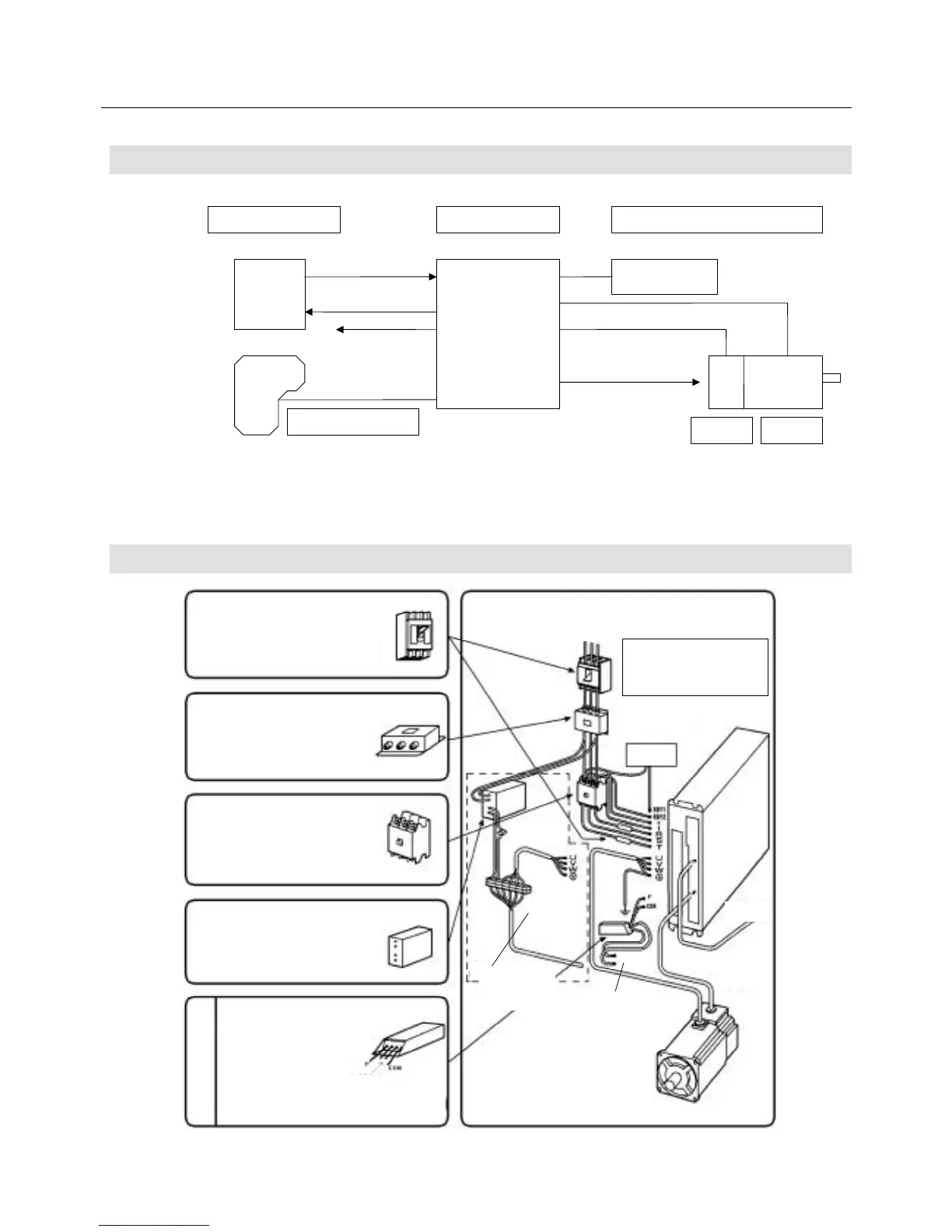
3.1 Block Diagram
Fig. 3-1 System Configuration Schematic Diagram
3.2 External Mounting and Wiring Diagram
Optional
Use one when load with
large inertial is to be
operated or in other
necessary cases.
External regenerative
resistor
DC power supply for brake
Used when the Servomotor is equipped
with a brake.
Magnetic contactor (MC)
Turns the Servo Amplifier power on and
off. Install a spark killer on it.
(Equivalent to CRE-50500 of Okaya
Electric Industries Co., Ltd.)
Noise filter
Install a filter equivalent to the LF series
of Tokin Corporation to prevent
common mode noise and normal mode
noise.
Circuit breaker, fuse
Used to protect the power line.
On the “PY2” Servo Amplifiers, no fuse is
built in. Be sure to connect a fast-blown
fuse of the capacity indicated in the
external connection diagram.
To
controller
Power supply:
200 VAC 3
φ
50 Hz/60 Hz
200 VAC 1
φ
50 Hz/60 Hz
100 VAC 1
φ
50 Hz/60 Hz
See Fig. 6-1 in
“6 Operation”.
Brake control
relay
Safety
circuit
Encode
connector
Thermostat
contact output
Thermostat
contact output
The input power supply differs
depending on the specifications
of the amplifier and the motor.
Be sure to connect the power
supply within the specified range.
The wiring
required when the
motor is equipped
with a brake.
Fig. 3-2 External Mounting and Wiring Diagram
External regenerative resistorServo Amp.
Upper controller
Command
Feedback
Remote operator
Holding brake
excitation
timing output
Sensor Motor
AMP ready