White
Violet
Green
Brown
Blue
Plug
Shell
Plug
Shell
Note
2)
Note 1)
Shield
Note 3) + 5 DCV
Note 3) GND (0 V)
Note 2)
Note 1)
Note 3) +5 VDC
Note 3) GND (0 V)
Case Earth
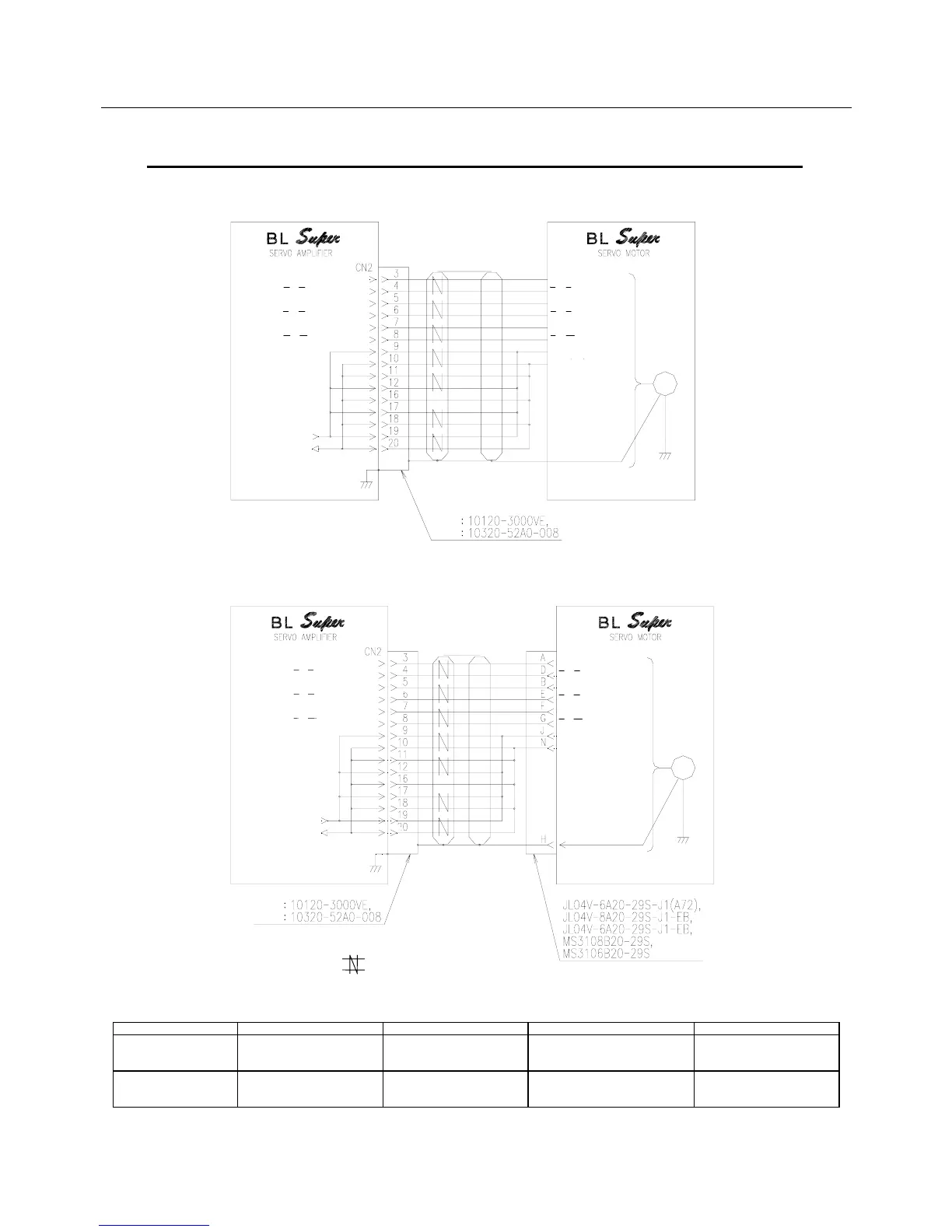
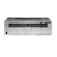
Incremental encoder (INC-E): Cannon plug type
Incremental encoder (INC-E): Lead wire type
A or U channel input
A or U channel input
B or V channel input
B or V channel input
C or W channel input
C or W channel input
Optical
Encoder
GND (0 V)
Sensor Incremental Encoder
+5 VDC
A or U channel output
A or U channel output
B or V channel output
B or V channel output
C or W channel output
C or W channel output
GND (0 V)
Optical
Encoder
Sensor Incremental Encoder
+5 VDC
A or U channel output
A or U channel output
B or V channel output
B or V channel output
C or W channel output
C or W channel output
A or U channel input
A or U channel input
B or V channel input
B or V channel input
C or W channel input
C or W channel input
4.3.3 Sensor Connection Diagram (INC-E Wiring-saved Incremental Encoder)
Notes: 1. For the parts marked , use a twisted pair shielded cable.
2. Refer to 4.6.2 CN1 & CN2 Shielding Procedure.
3. The sensor power connection differs depending on the cable length.
Refer to the following table.
Sensor cable length 5 m or less 10 m or less 20 m or less 30 m or less
+5 VDC wiring 19-pin connection
(9, 12 and 17 pins need not
be connected)
17- and 19-pin connection
(9 and 12 pins need not be
connected)
12-, 17- and 19-pin connection
(9 pin need not be connected)
9-, 12-, 17- and 19-pin
connection
GND (0 V) wiring 20-pin connection
(10, 11, 16 and 18 pins need
not be connected)
18- and 20-pin connection
(10, 11 and 16 pins need not
be connected)
11-, 18- and 20-pin connection
(10 and 16 pins need not be
connected)
10-, 11-, 16-, 18- and 20-pin
connection
Fig. 4-3 Sensor Connection Diagram (INC-E Wiring-saved Incremental Encoder)