Operating Instructions Stainless Steel In-Line Filter Holder Type 16274 13
Installation
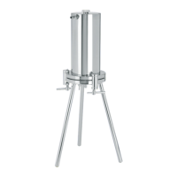
4 Installation
4.1 Scope of Delivery
Item Quantity
Lower part of device with 3 locking clamp screws 1
Lower part of the device 1
Stainless steel device leg 3
Filler opening cap 1
Valve 1
O-ring 2
Tube nozzle 2
Backflow prevention device 1
Filter support 1
Perforated sheet 1
Locking clamps 3
4.2 Selecting an Installation Site
Procedure
t Make sure that the following conditions are met at the installation site:
Condition Characteristics
Ambient conditions — Suitability tested (see Chapter “12.3
Ambient Conditions at the Installation
Site”, page 27 for ambient conditions)
Setup surface — Sufficiently dimensioned for the device and
the peripheral devices (for the space
requirements of the device, see
Chapter “12.2 Dimensions and Weight”,
page 27; for the peripheral device
space requirements, see instructions for
the peripheral devices, e.g. pressure tanks)
— Sufficient load-bearing capacity for the
device and the peripheral devices even
when full (for the device weight, see
Chapter “12.2 Dimensions and Weight”,
page 27; for the weight of the
peripheral devices, see the instructions for
the peripheral devices, e.g. pressure tanks)
Access to parts
relevant to operation
— Barrier-free